
Dynamic seal device

A dynamic sealing and sealing ring technology, applied in the direction of engine sealing, transmission parts, transmission boxes, etc., can solve the problems of short life, inability to withstand high pressure, inapplicability, etc., and achieve high service life, good sealing performance, and improved The effect of seal quality

Active Publication Date: 2008-05-28
靖江市华信科技创业园有限公司
View PDF0 Cites 10 Cited by
  • Summary
  • Abstract
  • Description
  • Claims
  • Application Information

AI Technical Summary

Problems solved by technology

Among them, felt seals and oil seals cannot withstand high-pressure working environments due to their low material hardness, and expansion ring seals require slots on the shaft, so the gap between the inner diameter of the expansion ring and the shaft cannot withstand high speeds , nor suitable for environments with high medium pressure
[0003] For the sealing between the high-speed rotating input / output shaft and the box, not only the sealing ring is required to be able to seal effectively, but also the sealing ring is required to maintain a sufficient life, which puts forward higher requirements for the sealing device. However, the above-mentioned various sealing The method has shortcomings such as short service life and inability to meet the occasions with high requirements for dynamic sealing.

Method used


Image

  • Dynamic seal device
  • Dynamic seal device
  • Dynamic seal device

Examples


Embodiment Construction

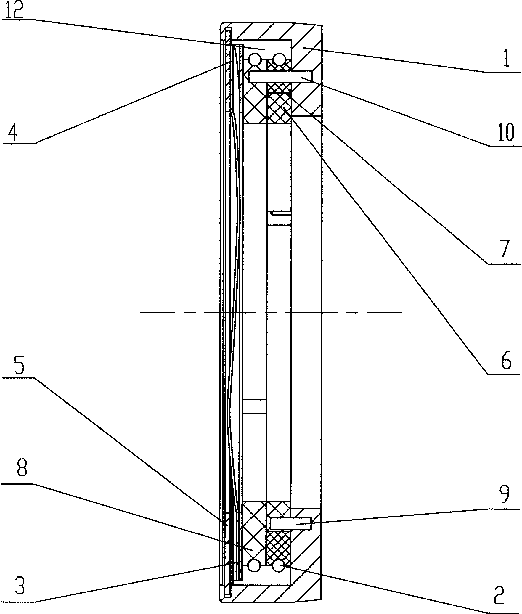
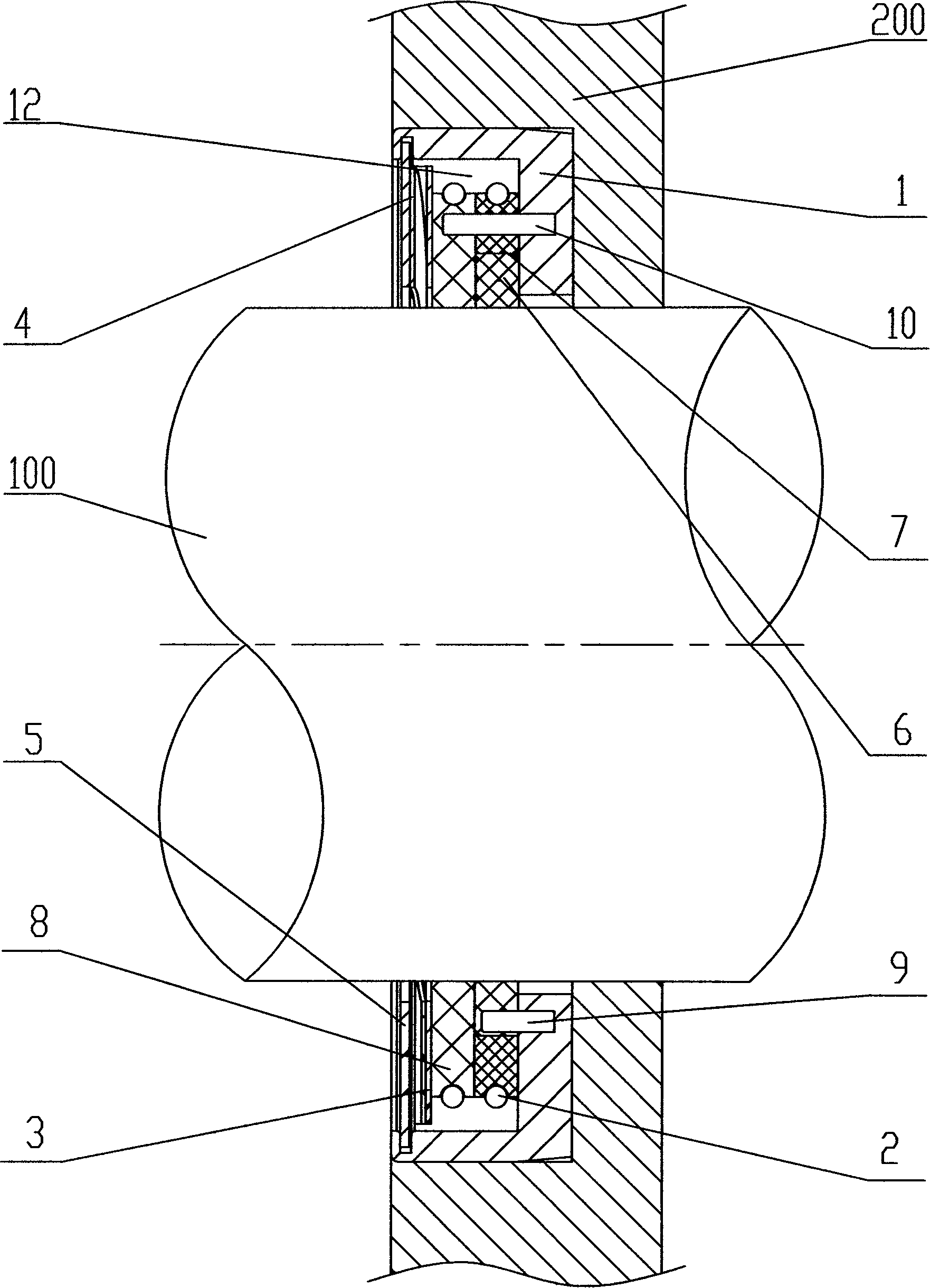
[0021] see figure 1 and figure 2 , is a preferred embodiment of the present invention. The dynamic sealing device of the present invention is installed between the rotating shaft 100 and the box body 200, and is sleeved on the rotating shaft 100. It includes a seat body 1, a sealing ring group, a spring ring 2, Adjust washer 3, spring washer 4 and pressure plate 5.

[0022] The seat body 1 is ring-shaped, and its outer end face is sunken inward to form a cavity 12. The sealing ring group, spring ring 2, adjustment washer 3, spring washer 4 and pressure plate 5 are all installed in the cavity of the seat body 1. cavity 12. An annular groove (not shown in the figure) is provided at the outermost end of the seat body 1 , that is, the open end of the cavity 12 , and the pressure plate 5 is located in the annular groove. The adjusting washer 3 and the spring washer 4 are located between the pressure plate 5 and the sealing ring set, wherein the adjusting washer 3 is stacked on ...


PUM


Abstract

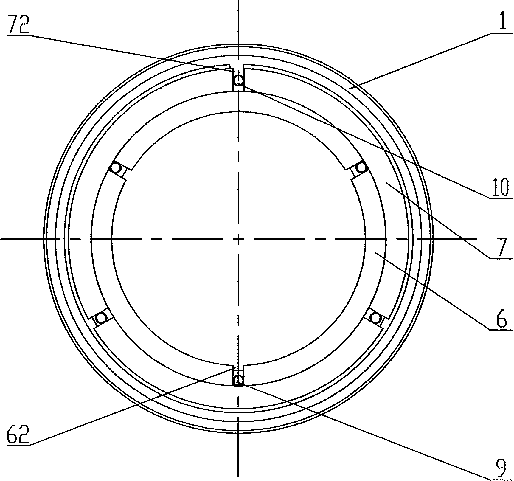
The invention relates to a dynamic seal device, which is installed between a rotating shaft and a box body, and is sleeved on the rotating shaft. The dynamic seal device comprises a ring-shaped base body, and a seal ring group which is located in the base body, wherein the seal ring group comprises an inner seal ring and an outer ring which are radially arranged along the rotating shaft. At least one slit is respectively opened on the inner seal ring and the outer seal ring, and the positions of the slits on the inner seal ring and the outer seal ring are mutually staggered. When the dynamic seal device with the structure is in working state, the axial motion and the radial motion can be kept, and the invention can freely float together with the rotating shaft. Therefore, the dynamic seal device of the invention has higher service life, and excellent seal property, which can meet the sealing needs of high temperature and high pressure.

Description

【Technical field】 [0001] The invention relates to a sealing device, in particular to a dynamic sealing device applied to the cooperation of a rotating shaft and a box body in a rotary transmission system. 【Background technique】 [0002] The sealing ring is the most commonly used sealing part in the rotary transmission device. At present, the dynamic sealing devices used in the rotary transmission device usually include felt seals, oil seals, and expansion ring seals. Among them, felt seals and oil seals cannot withstand high-pressure working environments due to their low material hardness, and expansion ring seals require slots on the shaft, so the gap between the inner diameter of the expansion ring and the shaft cannot withstand high speeds , It is also not suitable for environments with high medium pressure. [0003] For the sealing between the high-speed rotating input / output shaft and the box, not only the sealing ring is required to be able to seal effectively, but al...

Claims


Application Information

Patent Timeline
IPC IPC(8): F16J15/16F16H57/02F16H57/029
Inventor 韩志瑜
Owner 靖江市华信科技创业园有限公司
Learn More