Frequency converter output voltage detection circuit

An output voltage detection and output voltage technology, applied in the direction of measuring current/voltage, instruments, measuring devices, etc., can solve the problems of many megohm-level resistors and increased PCB cost, and achieve the goal of simplifying circuits, improving competitiveness, and reducing costs. Effect

Inactive Publication Date: 2008-05-28
SOMER LEROY ELECTRO TECH FUZHOU CO LTD
View PDF0 Cites 16 Cited by
  • Summary
  • Abstract
  • Description
  • Claims
  • Application Information

AI Technical Summary

Problems solved by technology

[0005] The purpose of the present invention is to provide a frequency converter output voltage detection ci

Method used


Image

  • Frequency converter output voltage detection circuit
  • Frequency converter output voltage detection circuit
  • Frequency converter output voltage detection circuit

Examples


Embodiment Construction

[0023] The present invention will be further described below based on the drawings and specific embodiments.

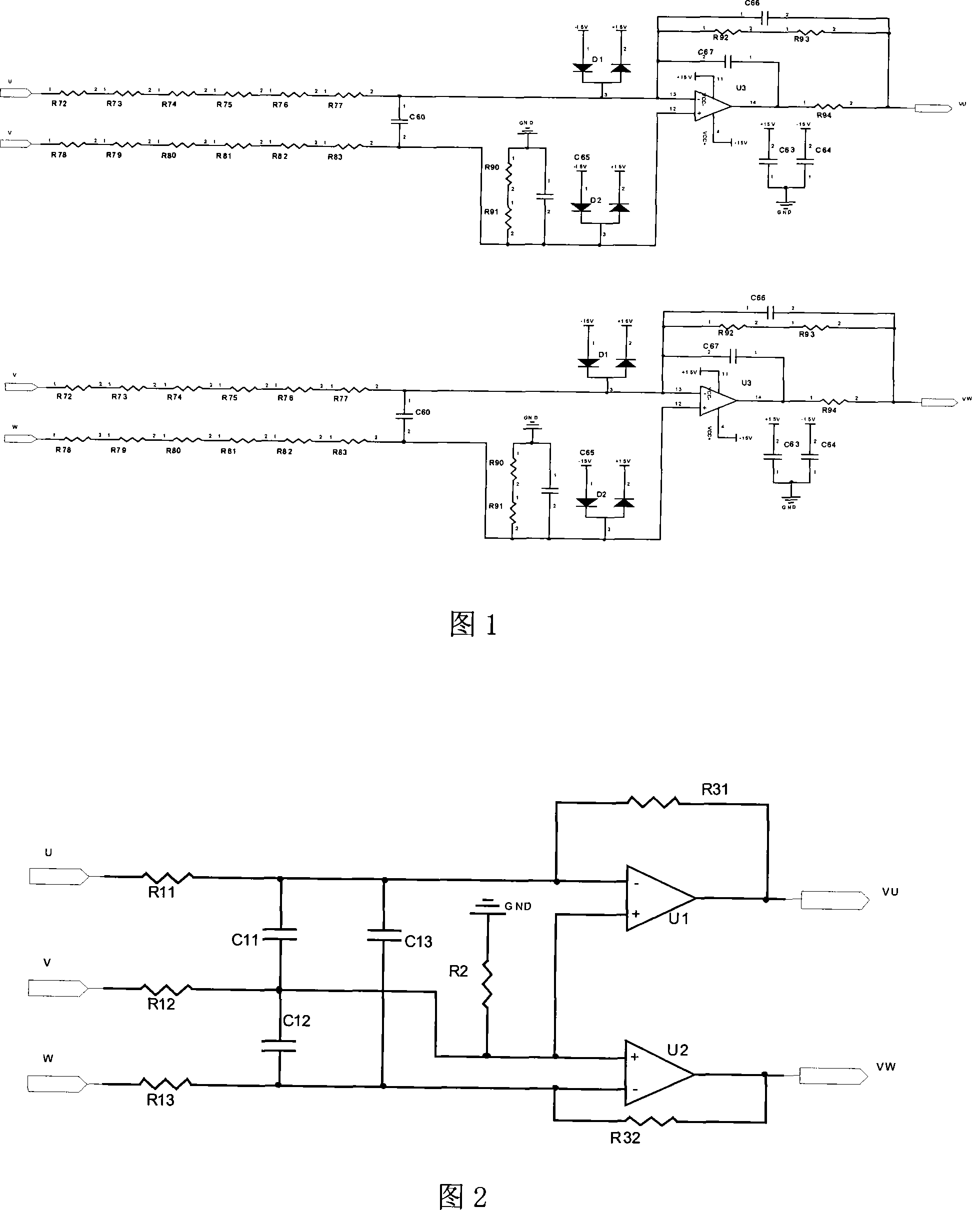
[0024]As shown in Figure 2, an inverter output voltage detection circuit includes U, V, W three-phase output voltage terminals and the VU, VW detection voltage terminals in the three-phase output voltage, and also includes connections to U, V, W The first to sixth voltage divider resistors (R11, R12, R13, R2, R31, R32), the first to third filter capacitors (C11, C12, C13) between the three-phase output voltage terminal and the VU and VW detection voltage terminals ) And the first and second comparison amplifiers (U1, U2); the first voltage dividing resistor R11 is connected in series with the U output voltage terminal, the second voltage dividing resistor R12 is connected in series with the V output voltage, and the third voltage dividing resistor R13 is connected in series with the W output voltage. , The first filter capacitor C11 is connected in parallel to both ends o...


PUM


Abstract

The invention discloses an inverter outputting voltage testing circuit, which comprises a U, V, W three-phase outputting voltage end and a VU, VW voltage testing end which can realize the three-phase outputting voltage, and also comprises a first to a sixth dividing potential electric resistances (R11, R12, R13, R2, R31, R32), a first to a third filter capacitors (C11, C12, C13), and a first and a second voltage comparers (U1, U2), which are connected between the U, V, W three-phase outputting voltage end and the VU, VW voltage testing end. The invention minimizes number of megohm-grade electrodes to 2/3 of original number through promoting existing technique under a condition that current circuit performance can be affected, which lowers cost, simplifies three-phase outputting voltage differential testing circuit, decreases products volumes, lowers products cost, and simultaneously increases products competitive power.

Description

Technical field [0001] The invention relates to a detection technology for the output voltage of a frequency converter, in particular to a detection circuit for the output voltage of the frequency converter. Background technique [0002] In the product design of frequency converter, UPS, power supply, etc. or other industrial applications, real-time detection of three-phase AC voltage is often required to achieve the needs of monitoring and control. The existing methods generally use megohm resistance jumper Between the strong current and the control circuit, in order to realize the isolation and voltage division between the two, the circuit form adopts a differential method, and the detection of each voltage corresponds to the respective differential circuit, as shown in Figure 1. [0003] The circuit realizes the voltage detection of VU and VW in the three-phase output voltage, where U, V, and W are the three-phase output voltage, VU, VW are the detection voltage output by the ...

Claims


Application Information

Patent Timeline
IPC IPC(8): G01R19/00G01R19/25
Inventor 廖海平董彪
Owner SOMER LEROY ELECTRO TECH FUZHOU CO LTD
Why Eureka
Try Eureka