Adjusting shaft arrangement of a turbocharger

A technology of turbocharger and shaft adjustment, applied in the direction of machine/engine, engine manufacturing, combustion engine, etc., can solve the problem of reducing the length of the gap seal, and achieve the effect of reducing exhaust gas and smoke

Inactive Publication Date: 2010-06-23
BORG WAMER CORP
View PDF5 Cites 0 Cited by
  • Summary
  • Abstract
  • Description
  • Claims
  • Application Information

AI Technical Summary

Problems solved by technology

[0005] However, this arrangement has an important disadvantage in that the slide-in bevel required for fitting the piston ring in the bushing bore significantly reduces the effective gap sealing length, since, in a symmetrical seal that is not transversely oriented In the construction and assembly of the bushing, a slide-in bevel on the other end face of the bushing is conveniently necessary

Method used


Image

  • Adjusting shaft arrangement of a turbocharger
  • Adjusting shaft arrangement of a turbocharger
  • Adjusting shaft arrangement of a turbocharger

Examples


Embodiment Construction

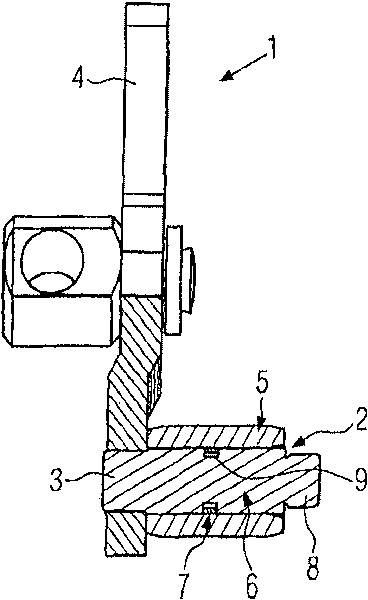
[0016] FIG. 1 shows a known adjusting shaft arrangement 1 of a VTG turbocharger. The VTG turbocharger itself is not shown in further detail in the figure, since this may comprise a conventional construction known per se.

[0017] The adjusting shaft arrangement 1 has an adjusting shaft 2 comprising a fixed part 3 and a free end 8 . Furthermore, FIG. 1 shows that the outer diameter of the fixed part 3 and the free end 8 is smaller than the main body 6 of the adjustment shaft 2 , said main body 6 being arranged between the fixed part 3 and the free end 8 . In this example all three parts have a cylindrical outer contour.

[0018] The adjusting shaft 2 is connected to a rod 4 via a fastening part 3 .

[0019] Furthermore, the adjusting shaft arrangement 1 has a bushing 5 which is arranged on the basic body 6 of the adjusting shaft.

[0020] Finally, a seal 7 is provided, which is arranged on the base body 6 between the bushing 5 and the adjustment shaft 2 . For this purpose, ...


PUM


Abstract

The invention relates to an adjusting shaft arrangement (1) of a variable turbine geometry turbocharger or waste gate turbocharger having an adjusting shaft (2) which has a fastening section (3); having a lever (4) which is connected to the adjusting shaft (2) via the fastening section (3); having a sleeve (5) which is arranged on a base body (6) of the adjusting shaft (2); and having a seal (7) which is arranged in the region of the base body (6) between the sleeve (5) and the adjusting shaft (2); the main body (6) of the adjusting shaft (2) having a stepped outer contour; and the sleeve (5)having an inner contour with a stepped inner contour which complements the design of the base body (6).

Description

technical field [0001] The invention relates to an adjusting shaft arrangement of a VTG turbocharger or a wastegate turbocharger. Background technique [0002] The term "VTG turbocharger" refers to a turbocharger with variable turbine geometry (VTG), which requires an adjustment shaft arrangement. In wastegate turbochargers, the turbine bypass is controlled by a valve that is moved by an adjusting shaft. [0003] In the arrangement of the adjusting shaft of known VTG turbochargers, depending on the applied positive exhaust pressure, the gap seal in the area between the adjusting shaft and the bushing may suffer from imperfect sealing, which may This causes the turbocharger to emit exhaust gas and smoke to the outside. [0004] An improved seal is known from WO 2004 / 063535 A1 by mounting a piston ring centrally in the bushing so that its sealing effect is combined with the gap sealing effect. [0005] However, this arrangement has an important disadvantage in that the slid...

Claims


Application Information

Patent Timeline
IPC IPC(8): F01D11/00F01D17/16F01D17/10F02B37/12
CPCF01D11/005F01D17/105F05D2220/40F05B2220/40F05D2250/293F01D17/165F05B2250/293F01D11/003F01D11/00F01D17/16F01D17/10
Inventor D·弗兰肯斯泰因V·保罗R·贝宁
Owner BORG WAMER CORP
Why Eureka
Try Eureka