Polishing pad and chemico-mechanical polishing method

A polishing pad and polishing surface technology, which is applied to surface polishing machine tools, grinding/polishing equipment, electrical components, etc., can solve the problems of difficult extraction of wafers, and the surface of wafers cannot meet the application requirements, etc., and achieve high surface smoothness degree of effect

Inactive Publication Date: 2008-06-04
SEMICON MFG INT (SHANGHAI) CORP +1
View PDF2 Cites 9 Cited by
  • Summary
  • Abstract
  • Description
  • Claims
  • Application Information

AI Technical Summary

Problems solved by technology

[0008] The problem to be solved by the present invention is that the surface of the wafer polished by the polishing pad in the prior art cannot meet the application requirements of optical devices for image transmission and products with higher requirements on the surface quality of the wafer, while the existing flat surface Wafers are difficult to pull out from the polishing surface after the polishing pad is polished

Method used


Image

  • Polishing pad and chemico-mechanical polishing method
  • Polishing pad and chemico-mechanical polishing method
  • Polishing pad and chemico-mechanical polishing method

Examples


Embodiment Construction

[0036] The specific implementation of the present invention will be described in detail below in conjunction with the accompanying drawings and specific embodiments.

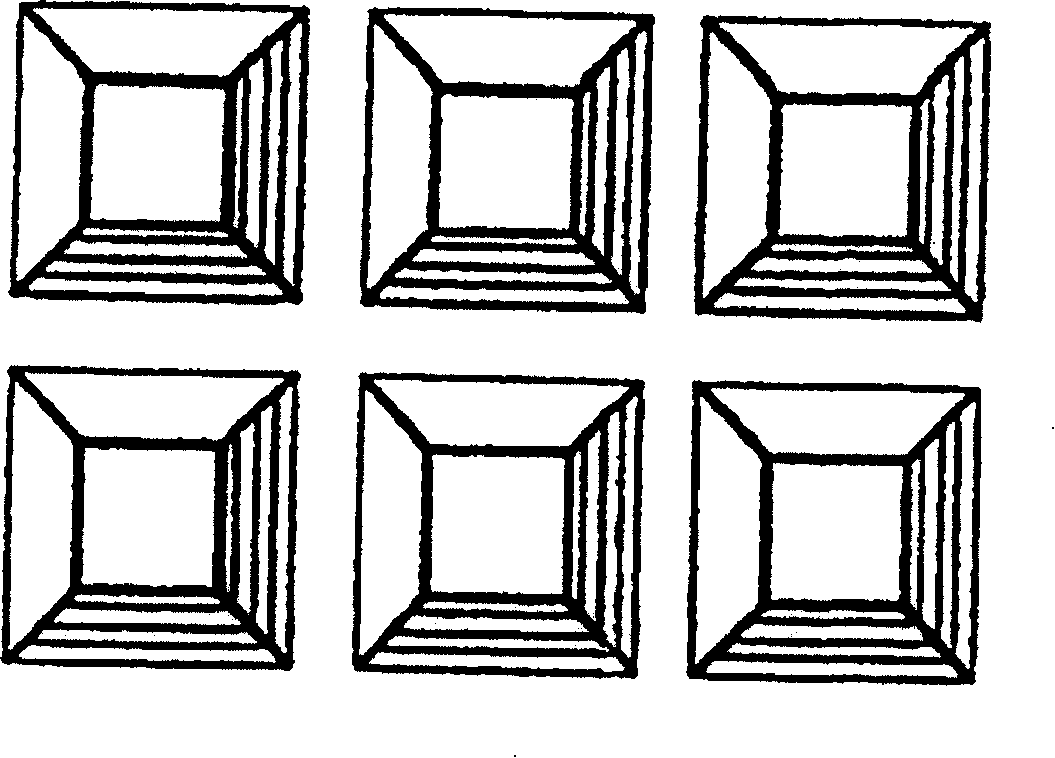
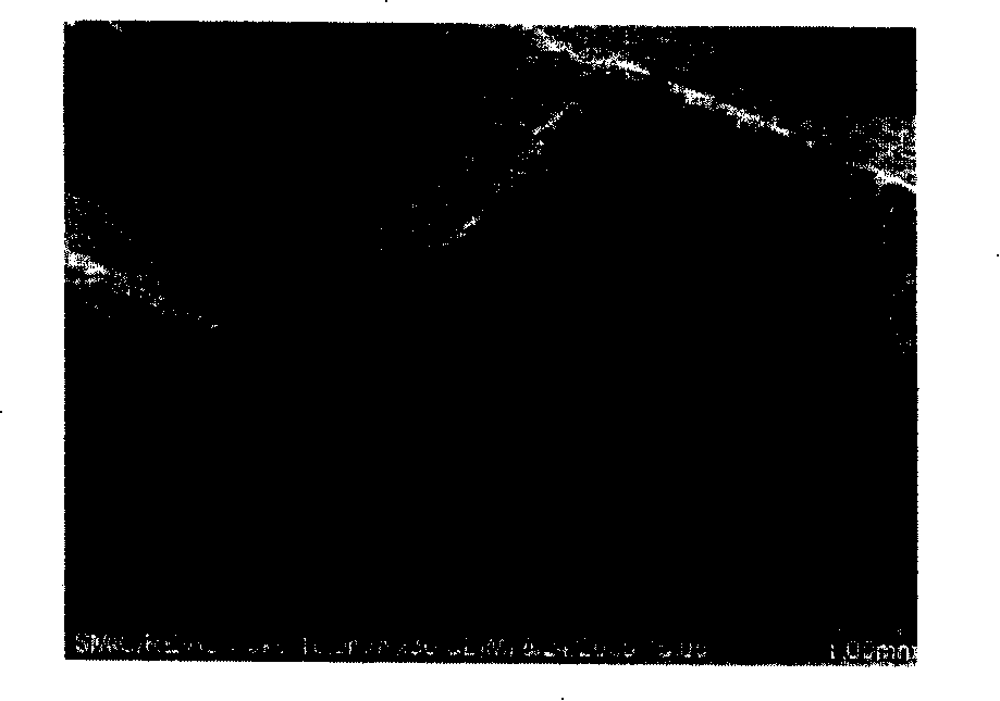
[0037] The polishing pads currently used in the chemical mechanical polishing process are all polishing pads with grooves on the polishing surface. After polishing the wafer with a polishing pad with grooves on the polishing surface, the flatness of the wafer surface cannot be applied to the device used for image transmission. In order to obtain a better flatness on the wafer surface, the present invention studies the reasons for the concaves on the wafer surface after chemical mechanical polishing. Observing the polishing pad with concave parts on the polishing surface through electron microscope, it is found that the microstructure of the concave parts on the polishing surface is as follows: image 3 As shown, the recess can be clearly seen from the figure.

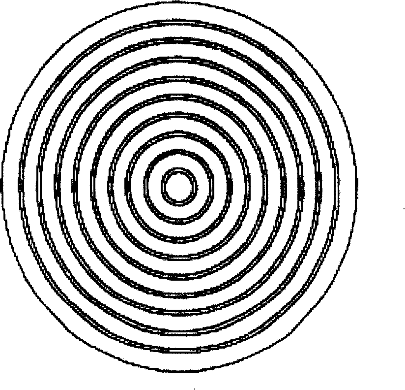
[0038] to have as figure 2 After the polishing ...


PUM


Abstract

The invention provides a polishing pad; the polishing surface of the polishing pad is provided with a plane area and a concave / convex area; the plane area is a flat surface with the coarseness less than 20 Mu m used for polishing wafer; the concave / convex area is provided with troughs or holes or the combination of the troughs and holes used for pulling the wafer out of the polishing surface. By adopting the polishing pad provided by the invention, the wafer after chemically and mechanically polished has high surface smoothness; after the polishing is finished, the wafer is moved to the concave / convex area of the polishing pad and the wafer is easy to be pulled out of the surface of the polishing pad.

Description

technical field [0001] The invention relates to a semiconductor chemical mechanical polishing process, in particular to a chemical mechanical polishing pad and a chemical mechanical polishing method for high flatness of the wafer surface. Background technique [0002] The chemical mechanical polishing (CMP) process was introduced into the integrated circuit manufacturing industry by IBM in 1984, and was first used in the planarization of the intermetallic insulating dielectric (IMD) in the subsequent process, and then used for tungsten (W) through the improvement of equipment and processes. planarization for shallow trench isolation (STI) and copper (Cu) planarization. Chemical Mechanical Polishing (CMP) is the fastest growing and most important technology in IC manufacturing process in recent years. [0003] The CMP polishing process uses mechanical force to act on the surface of the wafer in the atmospheric environment of the clean room, and generates power to break and c...

Claims


Application Information

Patent Timeline
Patent Type & Authority Applications(China)
IPC IPC(8): B24D17/00B24B29/00H01L21/304B24D99/00
CPCB24B37/26
Inventor 蒋莉臧伟季华小池正博
Owner SEMICON MFG INT (SHANGHAI) CORP
Why Eureka
Try Eureka