Ratchet type braking device

A braking device and ratchet-type technology, which is applied in the manufacture of tools, presses, etc., can solve problems such as difficult maintenance, difficulty in ensuring the effect of emergency braking, and long stopping strokes

Inactive Publication Date: 2011-05-11
张玉龙
View PDF6 Cites 0 Cited by
  • Summary
  • Abstract
  • Description
  • Claims
  • Application Information

AI Technical Summary

Problems solved by technology

[0002] At present, the rigid press uses the clutch to control the cam block through the electromagnet to block the tail handle of the rotary key, so that the press stops at the top dead center. When an accident occurs, it cannot stop in an emergency. Although there is an emergency braking device, due to the There are many other parts, and the braking force must be transmitted step by step. In addition, the key is forced to be off the key, and the stop stroke is too long, which makes it difficult to ensure the effect of emergency braking. The manufacturing cost is relatively high and maintenance is difficult. Another example is the patented No. 01239060.7, the lever-embracing drum-type key-off key-off brake has a reasonable structure and good braking effect. Since the brake belt cannot fully embrace the drum, the braking force generated is small, and it can only be applied to small-tonnage punching machines. There is a defect that it is difficult to achieve emergency braking or the braking effect is poor on punches larger than 40 tons

Method used


Image

  • Ratchet type braking device
  • Ratchet type braking device

Examples


Embodiment Construction

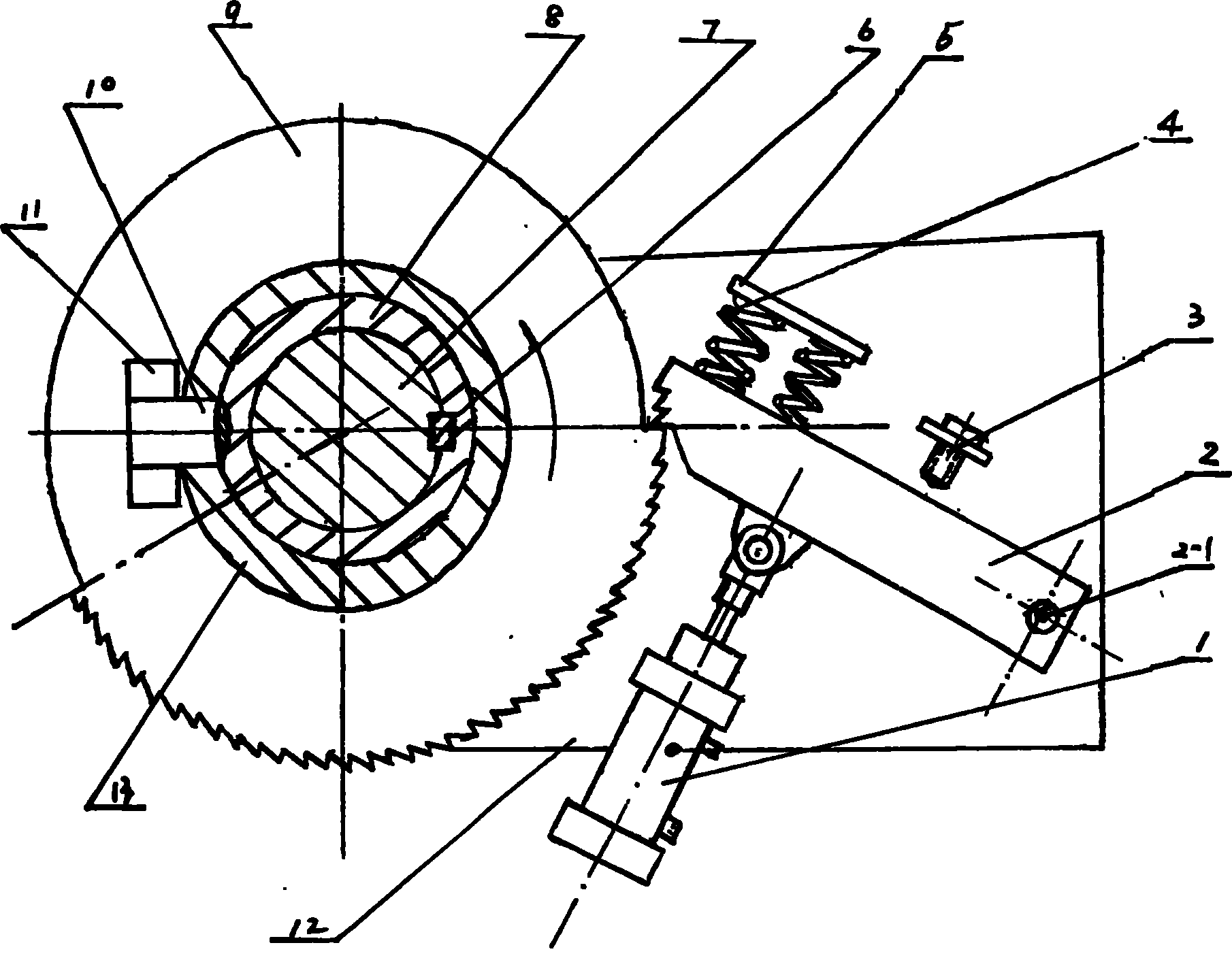
[0006] The present invention will be further described below in conjunction with accompanying drawing:

[0007] See attached figure 1 , the whole device is located between the flywheel and one side of the bed, the mounting plate (12) is fixed with a round pin (2-1), and the round pin (2-1) is flexibly connected to the ratchet (2), and the ratchet (2) A spring (4) is arranged between the spring seat (5), and the lower end of the ratchet (2) is connected with the cylinder (1). Within the range of 135°, the crankshaft (7) fixes the cover (8) into one body through the key (6), and a rotary key (10) is arranged between the flywheel cover (13) and the cover (8), and the key of the rotary key (10) Handle buckle is provided with in the groove of block (11) on ratchet (9), and ratchet (9) is installed on the crankshaft (7), and flywheel is housed outside flywheel cover (13).

[0008] See attached figure 1 , the press starts, the flywheel rotates, the rotary key (10) is pulled by the...


PUM


Abstract

The invention discloses a ratchet typed braking device which comprises a structure including a cylinder, a round pin, a locating nail, a spring, a spring seat, a key, a crankshaft, a sleeve, a rotating key, a check block, a mounting panel and a flywheel sleeve. The mounting panel is fixed with the round pin, the spring seat and the locating nail; the round pin is movably connected with a pawl; the spring is arranged between the pawl and the spring seat; the lower end of the pawl is connected with an electromagnet or the cylinder; a spine wheel is emptily coated on the crankshaft. As the pitch of the spine teeth is short; the rotating key drawing is quick; the time of emergency braking is short and stable and reliable, when coupling with a photoelectric switch, the emergency braking can be promptly and effectively operated. The braking time is shorter than 30 percent of national related regulations; the happening of personal injury accidents is effectively prevented; and the life safety of people is practically protected.

Description

technical field [0001] The invention relates to a ratchet brake device, which relates to the technical field of brake devices for press machines, in particular to the technical field of brake devices for rigid press machines, and is applied to various punch machines. Background technique [0002] At present, the rigid press uses the clutch to control the cam block through the electromagnet to block the tail handle of the rotary key, so that the press stops at the top dead center. When an accident occurs, it cannot stop in an emergency. Although there is an emergency braking device, due to the There are many other parts, and the braking force must be transmitted step by step. In addition, the key is forced to be off the key, and the stop stroke is too long, which makes it difficult to ensure the effect of emergency braking. The manufacturing cost is relatively high and maintenance is difficult. Another example is the patented No. 01239060.7, the lever-embracing drum-type key-...

Claims


Application Information

Patent Timeline
Patent Type & Authority Patents(China)
IPC IPC(8): B30B15/10
Inventor 张金龙张跃光张玉龙
Owner 张玉龙
Why Eureka
Try Eureka