Air flow filling and sucking type foundation draining method

A drainage method and foundation technology, applied in infrastructure engineering, soil protection, construction, etc., can solve the problems of large pressure difference, the drainage effect cannot reach the expected effect, and the air pressure is small, so as to ensure the treatment quality and improve the drainage effect. , Easy to use and labor-saving effect

Inactive Publication Date: 2008-06-04
浙江宾王工程材料有限公司
View PDF0 Cites 12 Cited by
  • Summary
  • Abstract
  • Description
  • Claims
  • Application Information

AI Technical Summary

Problems solved by technology

[0006] With this drainage method, since the air is only drawn from the drainage body in one direction, the air cannot be replenished, so that the air pressure in the drainage body and the foundation is getting smaller and smaller, and the pressure difference with the outside world is getting bigger and bigger. With increasing suction force, after a period of suction, the air pressure in the drainage body is very small, and the suction is close to a stagnan

Method used


Image

  • Air flow filling and sucking type foundation draining method
  • Air flow filling and sucking type foundation draining method
  • Air flow filling and sucking type foundation draining method

Examples


Embodiment Construction

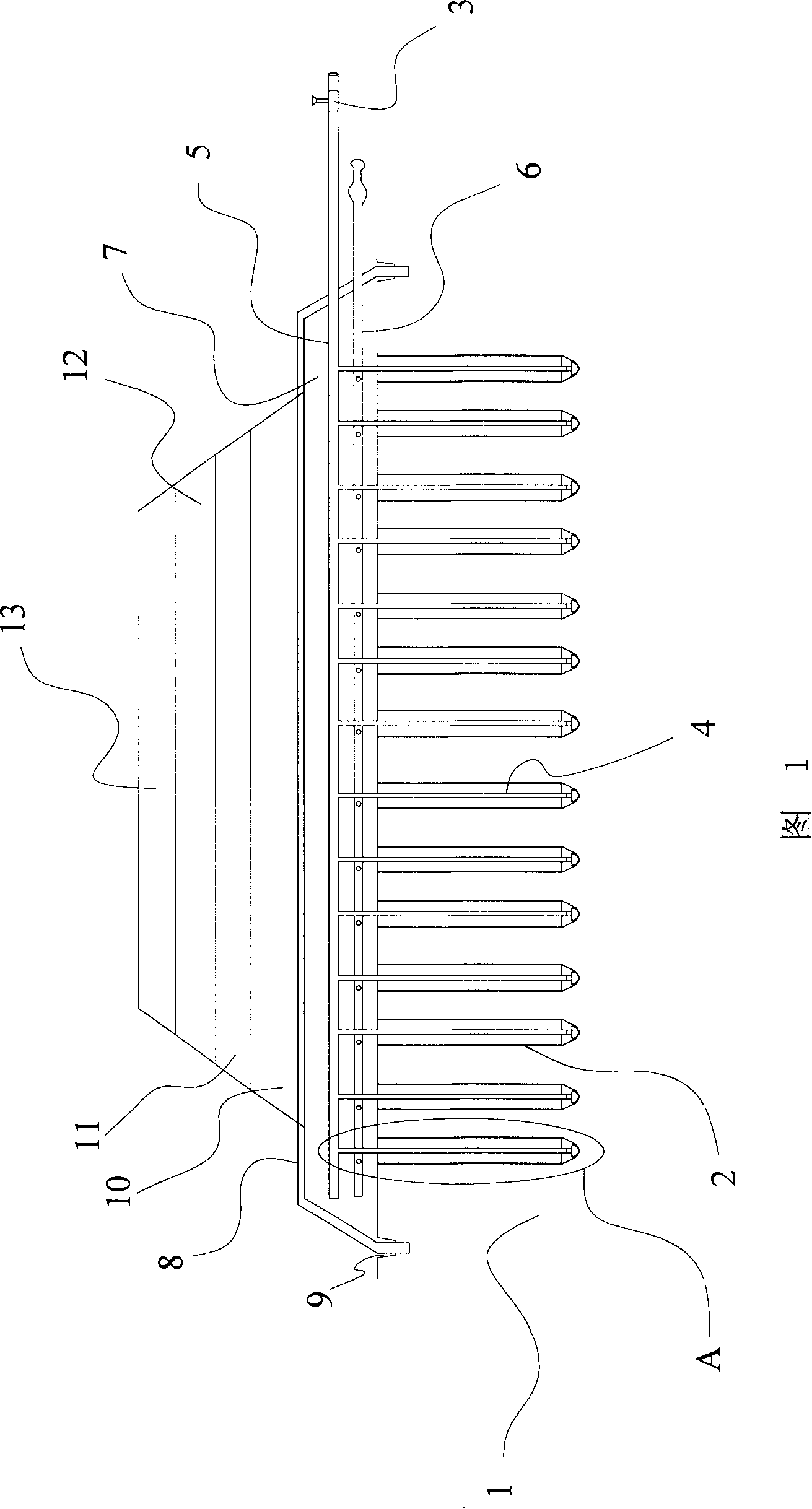
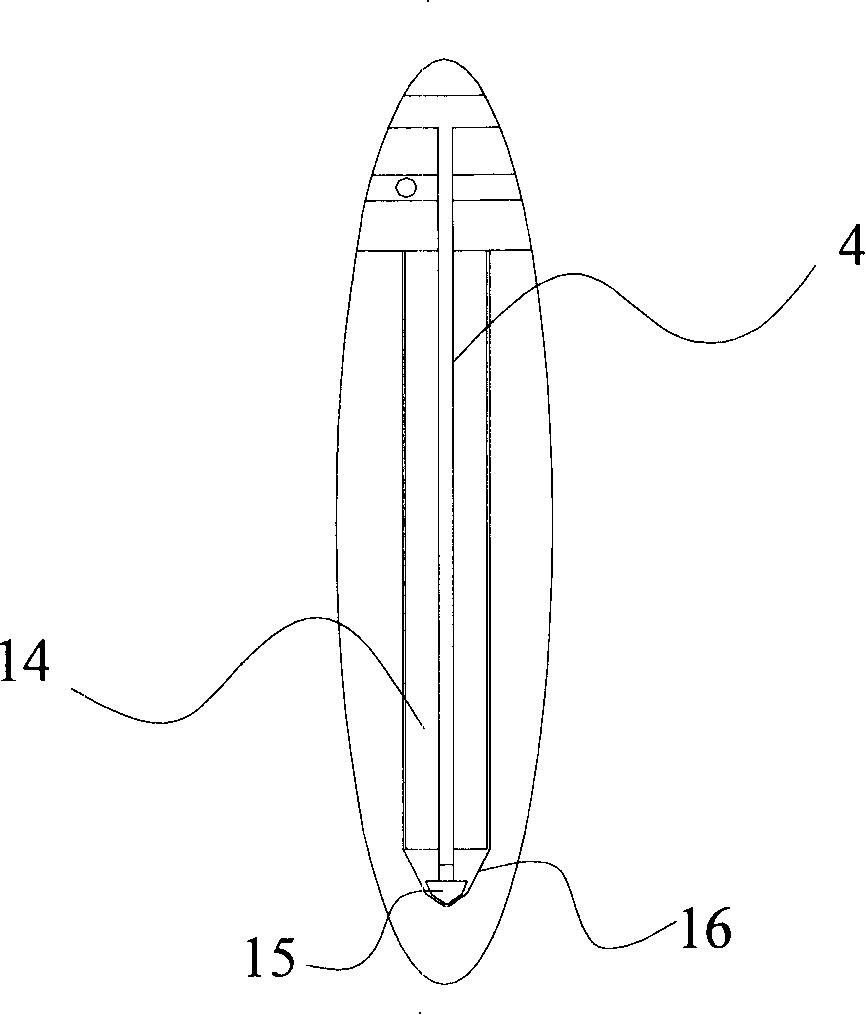
[0024] The implementation status of the airflow suction type foundation drainage method shown in Figures 1 and 2 is to embed a hollow pipe 4 of the same height in the drainage body 2 in advance, and the drainage body 2 can use the existing drainage board, and its core body Cut off a section from the lower end of 14 to expose the hollow tube 4, connect the auxiliary part 15 at the lower end of the hollow tube 4, then fasten the bottom of the filter membrane 16 or turn up and wrap the lower end of the core body 14 to form a filter membrane bag. The core body 14 can use the plastic plate or the plastic mesh plate that has drainage channel. The drainage channel can be a vertical guide groove on the plastic plate or a gap between mesh wires.

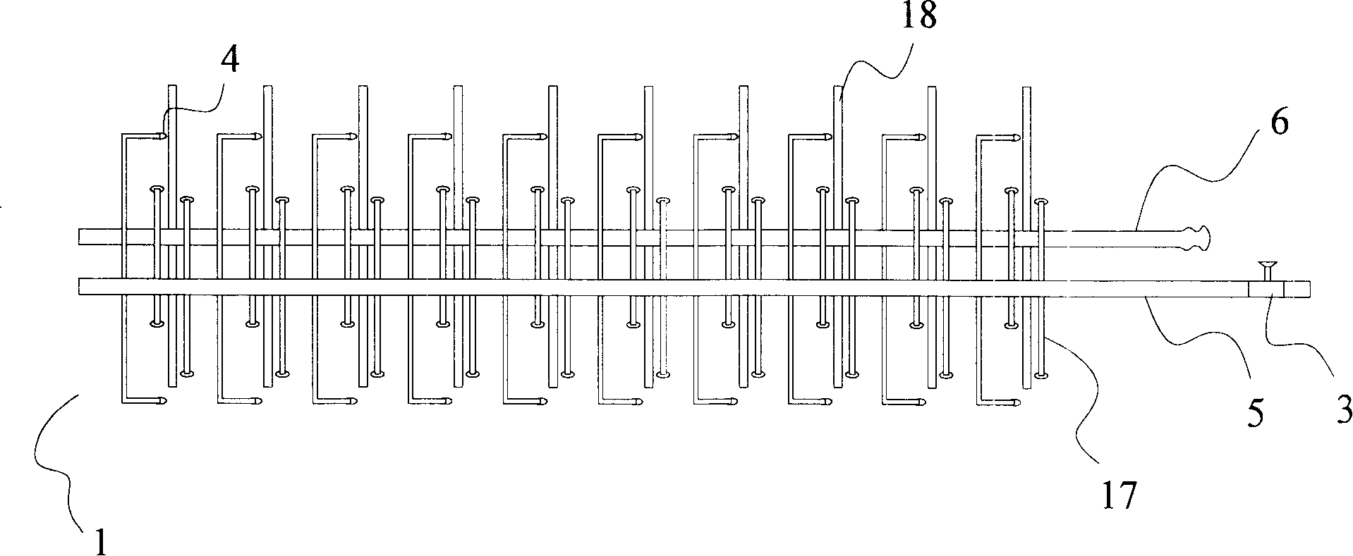
[0025] Then a plurality of drainage bodies 2 are vertically inserted into the foundation 1, and the upper ends of the hollow pipes of all drainage bodies 2 are connected with the intake main pipe 5 to form an intake pipe network, so that the ...


PUM

PropertyMeasurementUnit
Thicknessaaaaaaaaaa

Abstract

The invention provides air current suction type groundsill drainage, in particular a drainage in which an air current channel is formed inside a displacement hull by supplementing and pumping air so as to smoothly discharge the water content in the groundsill and to consolidate the groundsill. The prior art has the shortcomings of difficult drainage and bad effect. The invention has the following steps: 1. the displacement hull with a drainage channel is provided with at least one vertical hollow tubes inside; 2. the displacement hull with vertical hollow tubes is inserted into the groundsill; 3. the groundsill is pressed; 4. the air is led into the displacement hull from the hollow tubes and the air is pumped from the upper end of he drainage channel of the displacement hull, and the groundsill water is drained earthward along the displacement hull. The air can flow in the drainage system by forming the air current channel, thereby fulfilling the purposes of improving the drainage effect, being convenient to use by less labor, having good drainage effect and effectively guaranteeing the groundsill treatment quality.

Description

【Technical field】 [0001] The present invention relates to a treatment method for water-containing soft soil foundation, in particular to a drainage method that forms an airflow channel in the drainage body by supplementing the air and sucking the air, so as to smoothly discharge the water contained in the foundation and promote the consolidation of the foundation . 【Background technique】 [0002] The existing water-containing soft soil foundation drainage generally adopts the vacuum water absorption method, including the following steps: [0003] (1) Embedding at least one vertical vacuum drainage pipe in the drainage body (drainage board); [0004] (2) Insert the drainage body vertically into the foundation; [0005] (3) Suction air at the upper end of the vacuum tube of the drainage body, so that the water in the foundation is discharged along the drainage channel with the sucked air. [0006] With this drainage method, since the air is only drawn from the drainage body...

Claims


Application Information

Patent Timeline
IPC IPC(8): E02D3/10
Inventor 任再永
Owner 浙江宾王工程材料有限公司
Why Eureka
Try Eureka