Method for establishing OPC model

An optical proximity correction and model technology, which is applied to microlithography exposure equipment, photolithography exposure devices, electrical components, etc., can solve the problems of many adjustment steps and long simulation time, and achieve the reduction of adjustment steps and simulation The effect of shortening time

Active Publication Date: 2011-07-06
SEMICON MFG INT (SHANGHAI) CORP
View PDF3 Cites 2 Cited by
  • Summary
  • Abstract
  • Description
  • Claims
  • Application Information

AI Technical Summary

Problems solved by technology

[0008] In the existing method of making optical proximity correction models, since the step size is a fixed value, if there is a lot of intermediate data between the initial value and the end value, there will be too many adjustment steps and the simulation time will become longer

Method used


Image

  • Method for establishing OPC model
  • Method for establishing OPC model
  • Method for establishing OPC model

Examples


Embodiment Construction

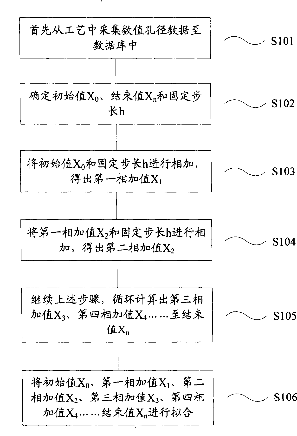
[0020] The linearization of photomask transmission requires the use of many variables, which requires a large amount of computing time to perform the calculation. In the prior art, since the step size is a fixed value, if there is a lot of intermediate data between the initial value and the end value, it will cause the number of steps to be adjusted. Too many and the simulation time becomes longer. Therefore, as the logical feature size decreases, it is necessary to provide a photomask implementation that accurately forms the desired image using the minimum calculation time. The present invention can adjust the number of steps because the step size can be adjusted according to the calculated slope. decrease, the simulation time becomes shorter. In order to make the above objects, features and advantages of the present invention more comprehensible, specific implementations of the present invention will be described in detail below in conjunction with the accompanying drawings....


PUM


Abstract

A method of building optical proximity correction model comprises the following steps of collecting optical proximity correction data to a database from processes, determining an initial value X0, an end value Xn and a fixed step size h, calculating initial value slope coefficient according to the initial value X0, obtaining an initial optimal step size Y0 according to the initial value slope coefficient, obtaining a first additive value X1 according to the initial value X0 and the initial optimal step size Y0, repeating the steps, working out a second additive valueX2, a third additive value X3,..., till the end value Xn, fitting the initial value X0, the first additive value X1, the second additive value X2, the third additive value X3,..., till an n-1 additive value and the end value Xn. Through the above steps, as step size values can be regulated according to the slope coefficient worked out, regulation step number can be reduced and simulation time is shortened.

Description

technical field [0001] The invention relates to a semiconductor manufacturing process, in particular to a photomask data processing technology, in particular to establishing an optical proximity correction model. Background technique [0002] Current implementations of photomask data bias are typically based on models that have been calibrated in a specific lithographic process, commonly referred to as optical proximity correction models. For example, correction of optical proximity effects (OPE) often requires attempts to "calibrate" the lithographic process in order to compensate for OPE. Existing techniques include associating so-called calibration parameters with an optical proximity correction model, which requires performing a detailed set of optical parameter measurements at different feature locations. The more measurement data collected, the better the accuracy of the calibration parameters. However, reliable optical proximity correction model parameter calibratio...

Claims


Application Information

Patent Timeline
Patent Type & Authority Patents(China)
IPC IPC(8): G03F7/20H01L21/027
Inventor 刘庆炜魏芳
Owner SEMICON MFG INT (SHANGHAI) CORP
Why Eureka
Try Eureka