Motor

A shaft tube and magnetic component technology, applied in the field of motors that can effectively improve electromagnetic effects, can solve problems such as poor electromagnetic effects, hot coils, and high-frequency noise, so as to improve the characteristics and overall performance of the motor, avoid hot coils, The effect of avoiding high-frequency noise

Inactive Publication Date: 2008-06-04
DELTA ELECTRONICS INC
View PDF0 Cites 2 Cited by
  • Summary
  • Abstract
  • Description
  • Claims
  • Application Information

AI Technical Summary

Problems solved by technology

However, due to the poor electromagnetic effect generated by the coreless coil group 15 and the magnetic ring 13, high-frequency noise is easily generated, and the required current is relatively large, causing the coil to become hot, thereby deteriorating the characteristics of the motor 1

Method used


Image

  • Motor
  • Motor

Examples


Embodiment Construction

[0018] A motor according to a preferred embodiment of the present invention will be described below with reference to related drawings.

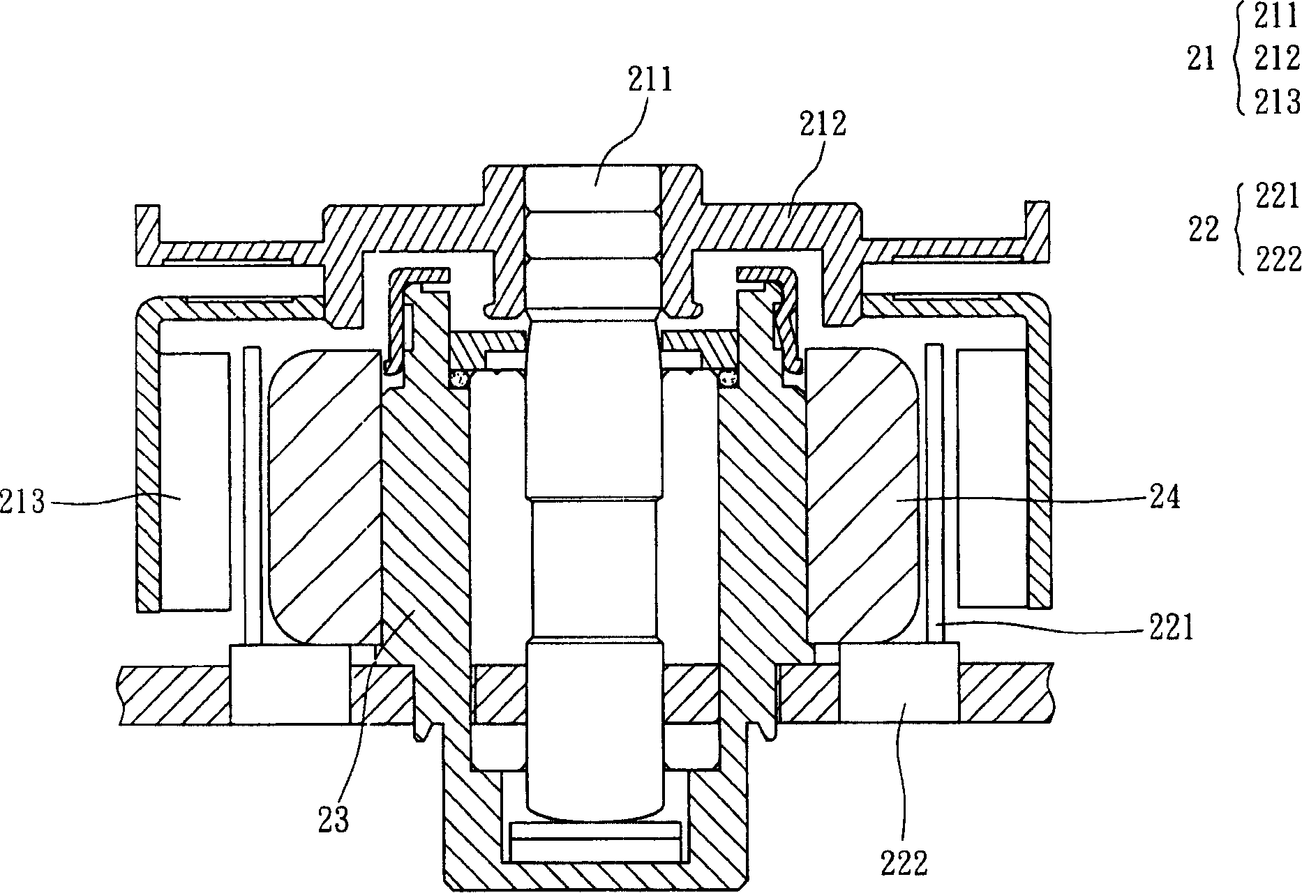
[0019] Please refer to figure 2 As shown, a motor 2 according to a preferred embodiment of the present invention includes a rotor structure 21 , a stator structure 22 and a shaft tube portion 23 , and the motor 2 can be applied to a fan. Wherein, the rotor structure 21 has a rotating shaft 211, a magnetically conductive shell 212 and a magnetic component 213, the rotating shaft 211 is connected with the magnetically conductive shell 212, and is arranged in the shaft tube portion 23, here, the rotating shaft 211 can be embedded or clamped or bonding with the magnetically permeable shell 212 . In addition, the magnetic component 213 is disposed around the inner wall of the magnetically conductive shell 212 , and the magnetic component 213 can be a magnetic ring.

[0020] The stator structure 22 has a coil assembly 221 and a driving circuit ...


PUM


Abstract

The invention relates to an electric motor which comprises an axis-tube component, a stator structure, a rotor structure and a magnetic body. The stator structure is arranged on the axis-tube component; the rotor structure has a rotating shaft and a magnetic component; the rotating shaft is arranged in the axis-tube component; the magnetic component is arranged correspondingly to the stator structure; the magnetic body is arranged between the rotor structure and the axis-tube component.

Description

technical field [0001] The invention relates to a motor, in particular to a motor which can effectively improve the electromagnetic effect. Background technique [0002] Motors are components that convert electrical energy into mechanical energy, and have been widely used in mechanical structures in daily life, such as fans, optical drives, or hard disk drives. Although there are many types of motors, the principle of their main application is the electromagnetic effect. [0003] Please refer to figure 1 As shown, a conventional motor 1 includes a rotating shaft 11 , a magnetic shell 12 , a magnetic ring 13 and a shaft tube 14 . Wherein, the rotating shaft 11 is connected to the magnetic conduction shell 12 and arranged in the shaft tube portion 14, and the magnetic ring 13 is connected to the inner wall of the magnetic conduction shell 12; in addition, the motor 1 has a coreless coil group (coreless coil) 15, its It is arranged between the shaft tube portion 14 and the m...

Claims


Application Information

Patent Timeline
Patent Type & Authority Applications(China)
IPC IPC(8): H02K1/12H02K1/02H02K3/04H02K1/27H02K1/28
Inventor 张绍雄陈立铭
Owner DELTA ELECTRONICS INC
Why Eureka
Try Eureka