Lamp tube status judgement circuit and its controller

A technology for judging circuits and controllers, applied in the direction of electric light sources, electrical components, lighting devices, etc., can solve the problems of adding lamps, the difficulty of detecting lamp status, and the lack of structure in general products.

Inactive Publication Date: 2008-06-04
BEYOND INNOVATION TECH
View PDF0 Cites 17 Cited by
  • Summary
  • Abstract
  • Description
  • Claims
  • Application Information

AI Technical Summary

Problems solved by technology

Moreover, the capacitor Clk has a smaller impedance at the higher frequency of the lamp lighting frequency, and more lamp current flows out through the equivalent capacitor Clk, making it more difficult to detect the lamp state.
In addition, the longer the length of the fluorescent tube, the more possible leakage current paths, all of which increase the difficulty of judging whether the tube is turned on or not.
[0007] It can be seen that the above-mentioned existing DC/AC conversion f

Method used


Image

  • Lamp tube status judgement circuit and its controller
  • Lamp tube status judgement circuit and its controller
  • Lamp tube status judgement circuit and its controller

Examples


Embodiment Construction

[0072] In order to further explain the technical means and effects of the present invention to achieve the intended purpose of the invention, the specific implementation and structure of the lamp state judging circuit and its controller according to the present invention will be described below in conjunction with the accompanying drawings and preferred embodiments. , features and their effects are described in detail below.

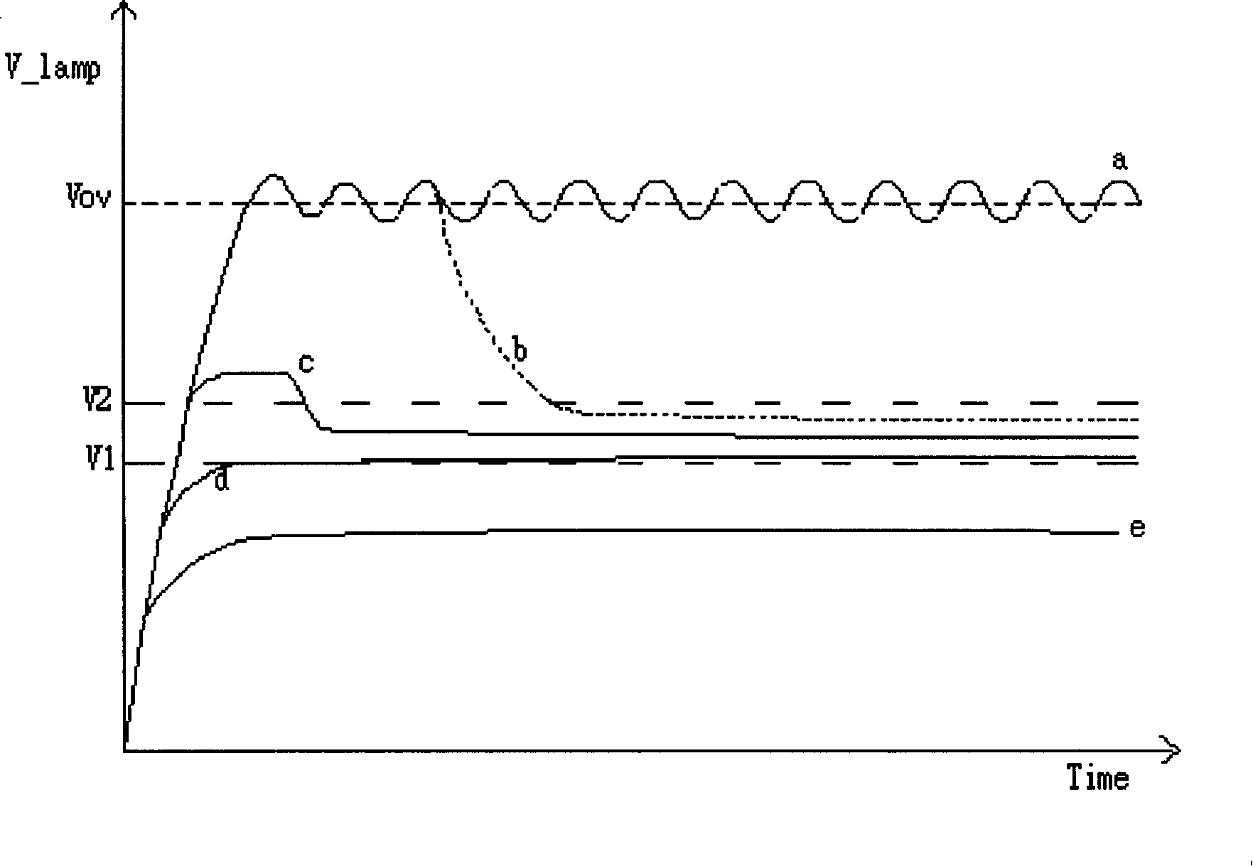
[0073] see image 3 , is the possible starting conditions of general fluorescent lamps, where the curves a and e are the cases where the lamps fail to light up, while the curves b, c and d are the cases where the lights are successful. In the case of curve a, the lamp tube is damaged, so although a sufficient voltage Vov (the maximum voltage for lighting the lamp tube) is provided, the fluorescent tube still cannot be lit and the voltage of the lamp tube remains at Vov. The situation of curve b is generally in the environment that is difficult to light ...


PUM


Abstract

The invention relates to a DC/AC conversion circuit for driving a load. The DC/AC conversion drive circuit comprises a switch device, a resonant groove, a voltage detection circuit and a controller. The switch device is coupled with a DC power. The resonant groove is coupled with the switch device and the load which converts the electric power of the DC power from the switch device into an AC signal in order to drive the load. The voltage detection circuit is coupled with the load and generates a voltage detection signal according the load voltage. The controller is coupled with the voltage detection circuit and the switch device and controls the electric power of the DC power that is transmitted to the resonant groove through the switch device. The controller decides the change of the operating frequency on the basis of the voltage detection signals.

Description

technical field [0001] The invention relates to a DC / AC conversion fluorescent lamp drive circuit, in particular to a DC / AC conversion control circuit capable of frequency conversion according to the state of the lamp tube. Background technique [0002] In the typical prior art DC / AC conversion fluorescent tube drive circuit, generally referred to as inverter (inverter), most of them adopt full-bridge DC / AC conversion circuit, and cooperate with the filtering and boosting of the resonant tank. Voltage device, which can convert the input DC voltage source into high-voltage AC power to drive fluorescent tubes. In order to stabilize the light source of the fluorescent tube and not change the brightness with the change of the input voltage, most of its designs are equipped with a negative feedback control circuit to stabilize the operating current of the fluorescent tube. [0003] Since the driving voltage required before and after the fluorescent tube is lit is different, and ...

Claims


Application Information

Patent Timeline
IPC IPC(8): H05B41/14
Inventor 简焕文
Owner BEYOND INNOVATION TECH
Why Eureka
Try Eureka