
Substrate for light-emitting element packaging, luminescent module, and lighting apparatus

A technology of light-emitting elements and light-emitting modules, which is applied in the direction of lighting devices, components of lighting devices, semiconductor devices of light-emitting elements, etc., which can solve problems such as wiring damage, accelerated wiring insulation material thermal degradation, and large-scale devices. Large-area lighting device, good expandability, and good heat dissipation effect

Inactive Publication Date: 2008-06-04
FUJIKURA LTD
View PDF3 Cites 3 Cited by
  • Summary
  • Abstract
  • Description
  • Claims
  • Application Information

AI Technical Summary

Problems solved by technology

However, when more light-emitting modules are combined, detour arrangement and wiring are complicated for the substrate for mounting the light-emitting modules, resulting in an increase in cost
In addition, when the wiring is stored inside the lighting device in order to avoid damage to the wiring from the outside, the storage space limits the design of the lighting device.
[0008] In addition, especially for light-emitting modules using LEDs, the temperature of the substrate increases due to the heat generated by the LED element. Therefore, if wiring is mounted on the back of the substrate, there is a possibility of accelerating the thermal degradation of the insulating material of the wiring.
[0009] In addition, when wiring for transportation is formed on the surface of the substrate, other circuits have to be considered, so there is a problem that in order to ensure a sufficient wiring width, the width of the substrate itself needs to be enlarged, resulting in an increase in the size of the device.

Method used


Image

  • Substrate for light-emitting element packaging, luminescent module, and lighting apparatus
  • Substrate for light-emitting element packaging, luminescent module, and lighting apparatus
  • Substrate for light-emitting element packaging, luminescent module, and lighting apparatus

Examples


Embodiment Construction

[0025] Hereinafter, embodiments of the present invention will be described with reference to the drawings.

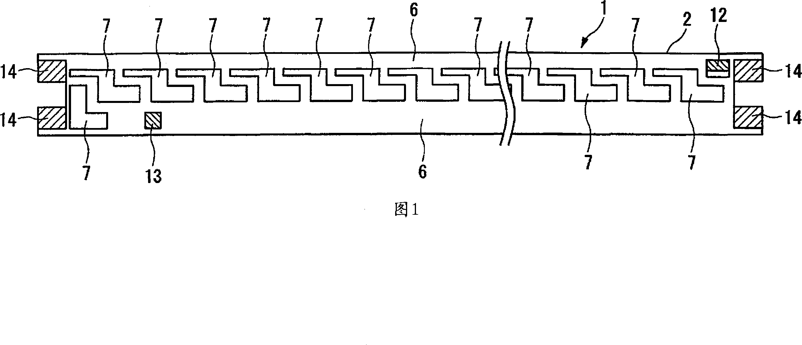
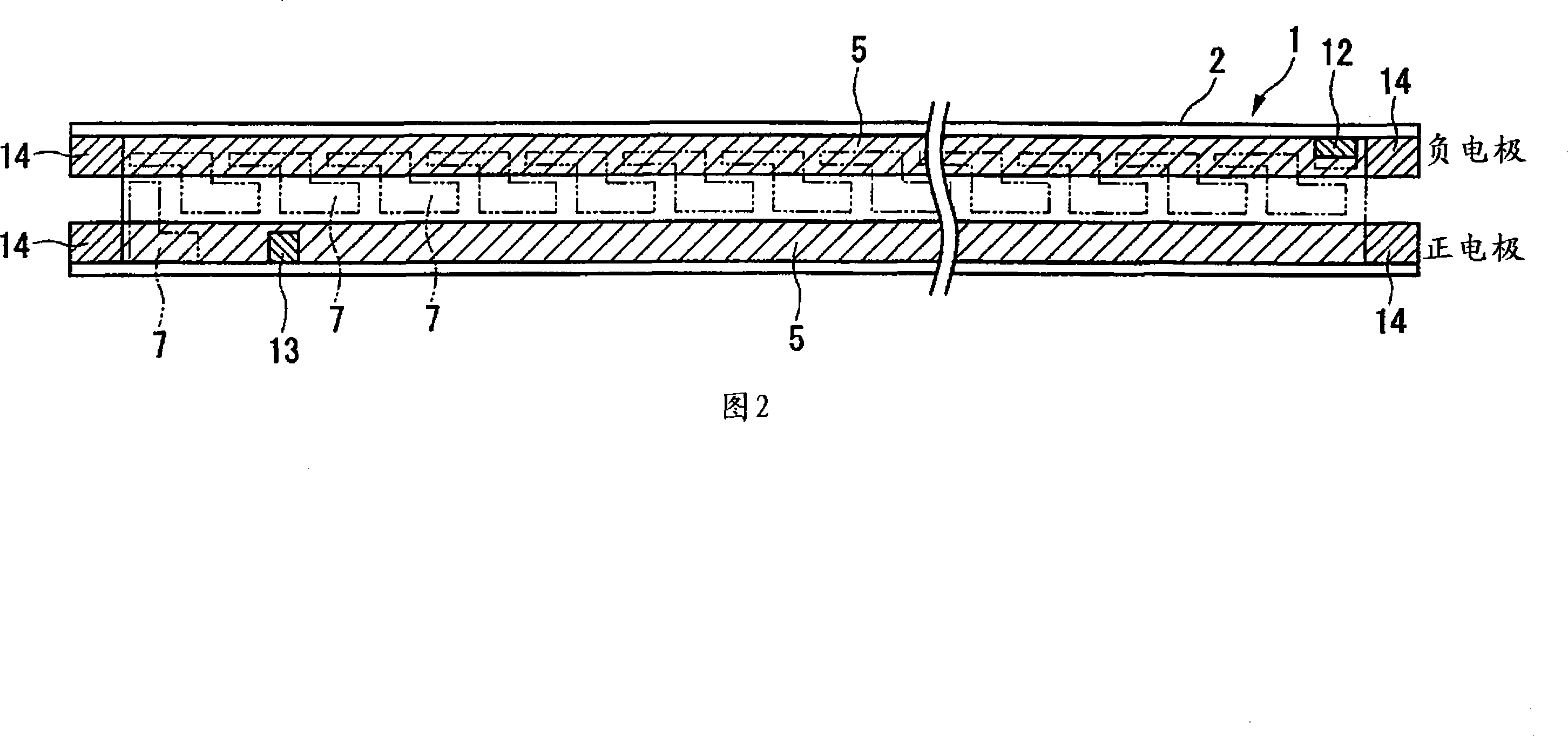
[0026] 1 and 2 are diagrams showing an embodiment of a substrate for mounting a light-emitting element of the present invention. FIG. 1 is a plan view of a substrate for mounting a light-emitting element 1, and FIG. Perspective view of the formation location of layer 5.

[0027] 3 and 4 are diagrams showing an embodiment of the light emitting module of the present invention, and FIG. 3 is a light emitting module 10 configured by mounting a plurality of light emitting elements 8 on the light emitting element mounting substrate 1 shown in FIG. 1 . In the top view, FIG. 4 is a cross-sectional view of the light emitting module 10 .

[0028] The light-emitting element mounting substrate 1 of the present embodiment is formed by laminating the first conductive layer 5, the second enamel layer 6, and the second conductive layer on the outside of the enamel substrate 2 covered ...


PUM


Abstract

Substrate for mounting light emitting elements wherein two or more conductive layers and insulating layer provided between each conductive layer are formed on the outside of an enameled substrate, which is an enamel layer covering the surface of a core metal. The conductive layer provided on the enamel layer side links one end of enameled substrate to the other end, feeds power to a plurality of light emitting elements mounted in the longitudinal direction of the conductive layer; and the conductive layer on the surface of a protruding section provided at both ends of the enameled substrate extends and forms a connection with another substrate. Light emitting module formed by mounting light emitting elements on this substrate.

Description

technical field [0001] The present invention relates to a light-emitting element mounting substrate for mounting light-emitting elements such as a plurality of light-emitting diodes (hereinafter referred to as LEDs), and particularly relates to a substrate capable of securing heat dissipation when light-emitting elements are mounted at a high density in applications such as lighting, A light-emitting element mounting substrate capable of supplying power to a plurality of light-emitting elements by using only a conductive layer in the substrate without additional detour wiring, a light-emitting module with light-emitting elements mounted on the substrate, and a lighting device having the light-emitting module. Background technique [0002] When a light-emitting module in which light-emitting elements such as LEDs are mounted on a substrate is used for lighting or the like, sufficient brightness cannot be obtained using one light-emitting module as a light source for lighting, ...

Claims


Application Information

Patent Timeline
Patent Type & Authority Applications(China)
IPC IPC(8): H01L33/00H05K1/05F21V19/00F21Y101/02F21V29/00H01L33/64
CPCH05K1/053H05K2201/10106F21K9/00H05K1/117H01L2224/45144H01L2224/48091H01L2224/73265H01L33/64H01L2924/00014H01L2924/00
Inventor 增子幸一郎
Owner FUJIKURA LTD
Learn More