Brick discharging machine

A technology of unloading brick machine and rack, applied in the direction of unloading device, manufacturing tools, etc., can solve the problems of complex structure of brick unloading machine, and achieve the effect of simple structure and convenient use.

Active Publication Date: 2008-06-11
福建省海源智能装备有限公司
View PDF2 Cites 14 Cited by
  • Summary
  • Abstract
  • Description
  • Claims
  • Application Information

AI Technical Summary

Problems solved by technology

However, such a brick unloading machine not only needs multiple pairs of manipulators to clamp each row of bricks, and closes them through the closing device, but also clamps them through the clamping mechanism on the manipulator, which is a movable splint in the vertical direction. , and drive the movable splint to move through multiple cylinders to keep the movable splint able to move in parallel to clamp the bricks. Therefore, the clamping and closing need to be carried out separately through different mechanisms, and the structure of the brick unloading machine is complicated.

Method used


Image

  • Brick discharging machine
  • Brick discharging machine
  • Brick discharging machine

Examples


Embodiment Construction

[0031] Best practice:

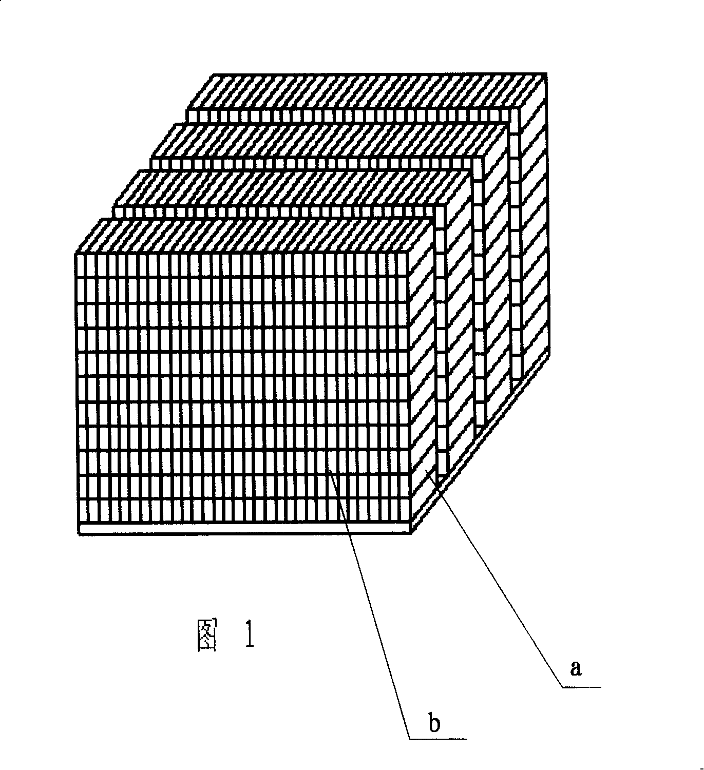
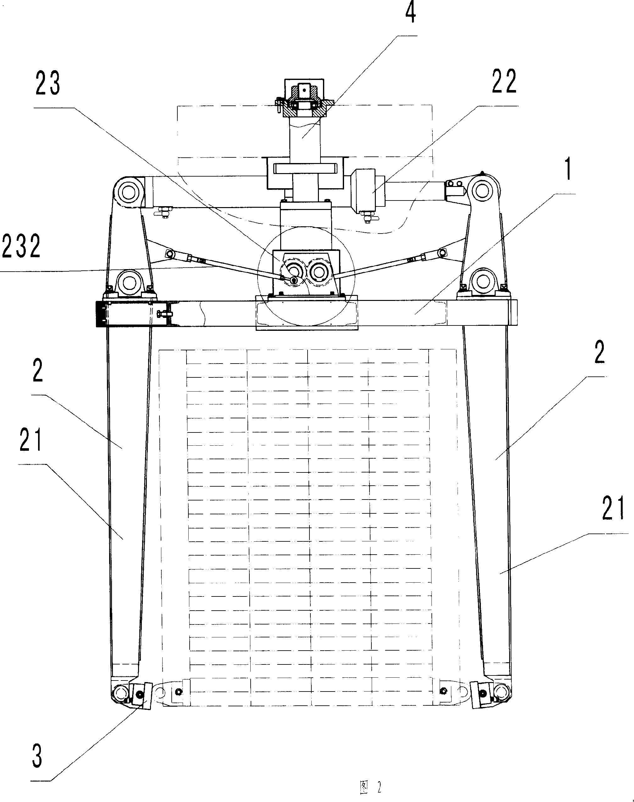
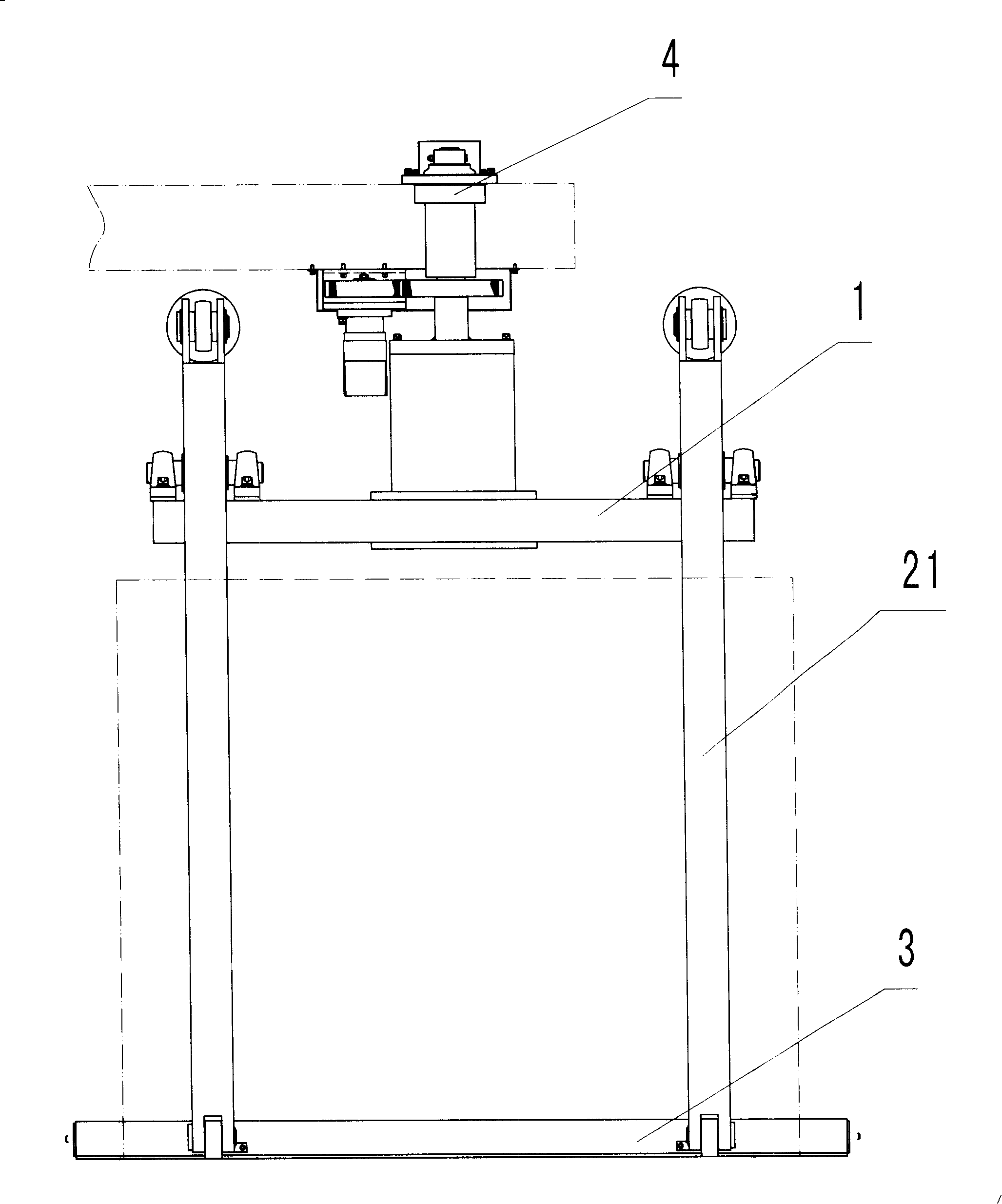
[0032] Referring to Figure 1, Figure 2, image 3 , a brick unloading machine, including a frame 1, a manipulator 2, at least two pairs of manipulators 2 are installed on the frame 1, a pair of manipulators 2 includes two clamping arms 21, a first power mechanism 22 and a synchronous limiter 23, clamping The arm 21 is hinged on the frame 1, the first power mechanism 22 and the synchronous limiter 23 are connected between the two clamp arms 21, and one clamp arm of a pair of manipulators is connected with the same side clamp arm of the other pair of manipulators. A clamping plate 3 is connected between the bottom ends of the clamping plates 3 and each clamping arm 21 is hinged. The hinge point between the clamp arm 21 and the frame 1 is located between the two ends of the clamp arm 21 , and the first power mechanism 22 and the synchronous limiting device 23 are located above the frame 1 and connected with the clamp arm 21 . The first power mechanism 22 i...


PUM


Abstract

The invention relates to a device for unloading formed products from apparatus, in particular to a brick-unloading machine, which comprises a frame and manipulators. The structural points of the invention are that at least two pairs of manipulators are mounted on the frame, one pair of the manipulator includes two arms, a first power mechanism and a synchronous locking apparatus, arms are hinged on the frame, the first power mechanism and the synchronous locking apparatus are connected in the position between the two arms, a plywood is arranged between the bottom ends of one arm of one pair of manipulator and the on-the-same-side arm of the other pair of manipulator, and the plywood is hinged with each arm. At the time of clamping bricks, the space among palletizing bricks is closed and removed, clamping bricks and closing are finished through the same mechanism, and the brick-unloading machine has simpler structure and more convenient use.

Description

technical field [0001] The invention relates to a device for discharging shaped products from the device, in particular to a brick unloading machine. Background technique [0002] In the brick production process of the prior art, after the bricks are formed, the bricks need to be stacked on the maintenance trolley for maintenance. The bricks stacked on the maintenance trolley are shown in Figure 1. In this way, after maintenance, the bricks need to be stacked Bricks are transported from the maintenance trolley to be stacked, but at present, it is carried by hand, which is labor-intensive and inefficient, which is not conducive to mechanized production, or it is carried by a brick unloading machine. The applicant has applied for a Chinese patent before this. , Patent No.: 200420150158.9, Name: Brick unloading machine, the brick unloading machine includes a linear guide rail, a closing device, a frame and a plurality of manipulators, the manipulator has a clamping mechanism, a...

Claims


Application Information

Patent Timeline
Patent Type & Authority Applications(China)
IPC IPC(8): B28B13/04
Inventor 李良光王琳
Owner 福建省海源智能装备有限公司
Why Eureka
Try Eureka