
Parking brake

A technology for parking brakes and rod components, which is applied in the direction of braking action starting devices, manual starting devices, brakes, etc., which can solve problems such as complicated assembly procedures and existing strength problems, and achieve strength problems, increase strength, The effect of reducing the number of components

Active Publication Date: 2008-06-11
HONDA MOTOR CO LTD
View PDF1 Cites 0 Cited by
  • Summary
  • Abstract
  • Description
  • Claims
  • Application Information

AI Technical Summary

Problems solved by technology

[0004] However, in any of the existing parking brake devices, the guide portion for guiding the wire is formed by a different member, and since the guide member is subjected to a large load when the operating lever is operated, it must be used. Any method such as welding securely joins the guide to the joystick side
In the case of fixing with this method, there is a problem in terms of strength
In addition, there is a problem that the assembly process is complicated by adding processes such as welding.

Method used


Image

  • Parking brake
  • Parking brake
  • Parking brake

Examples


Embodiment Construction

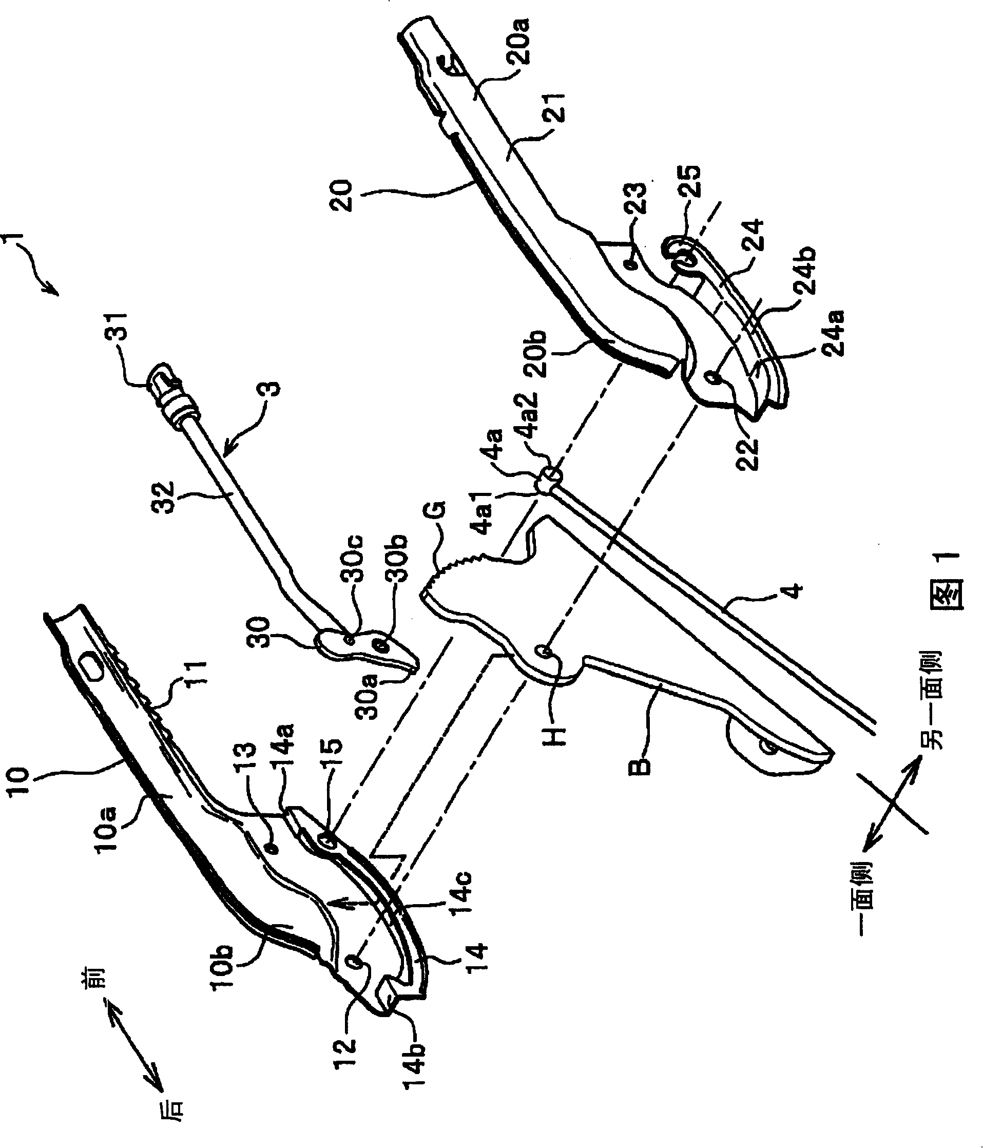
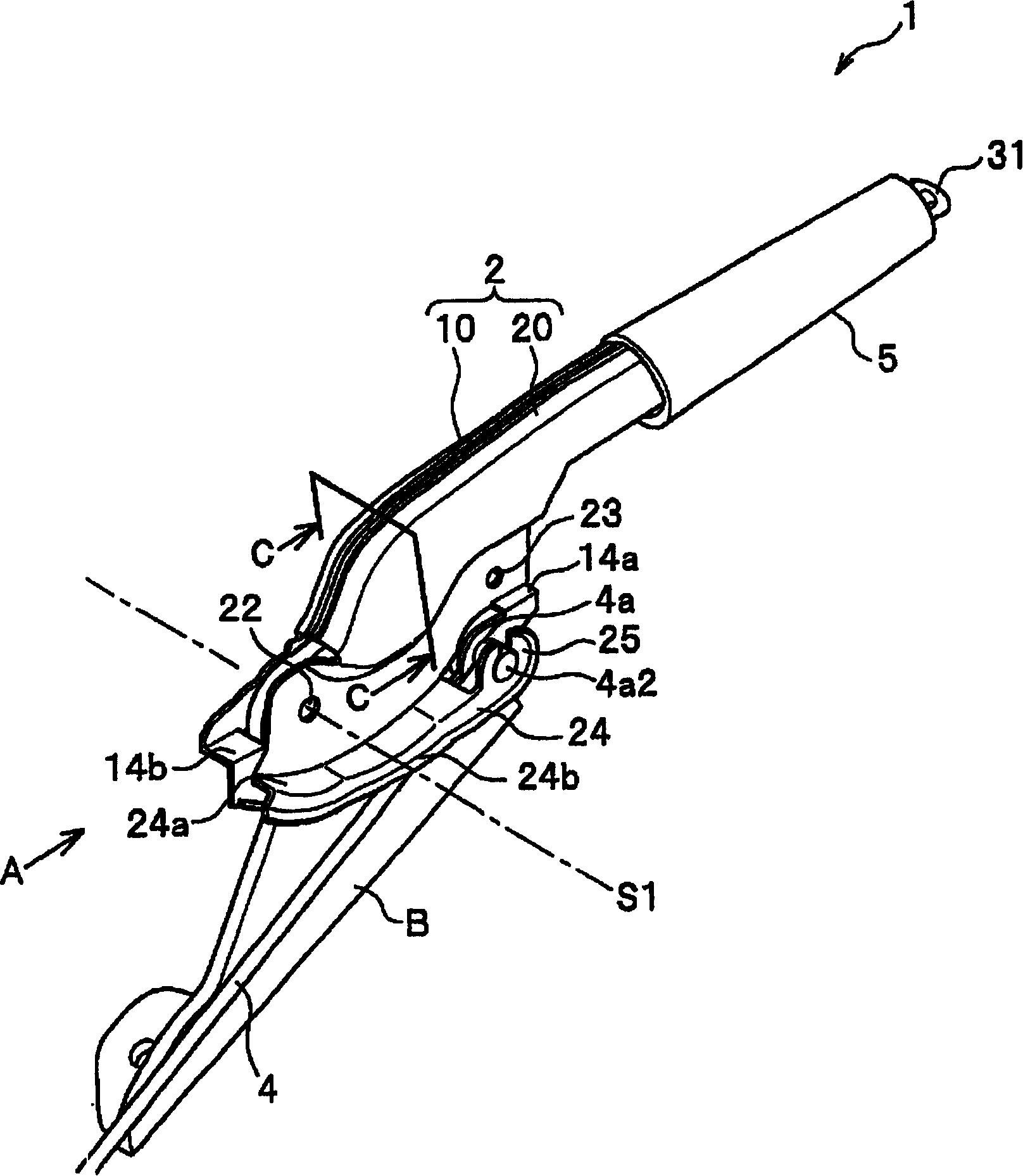
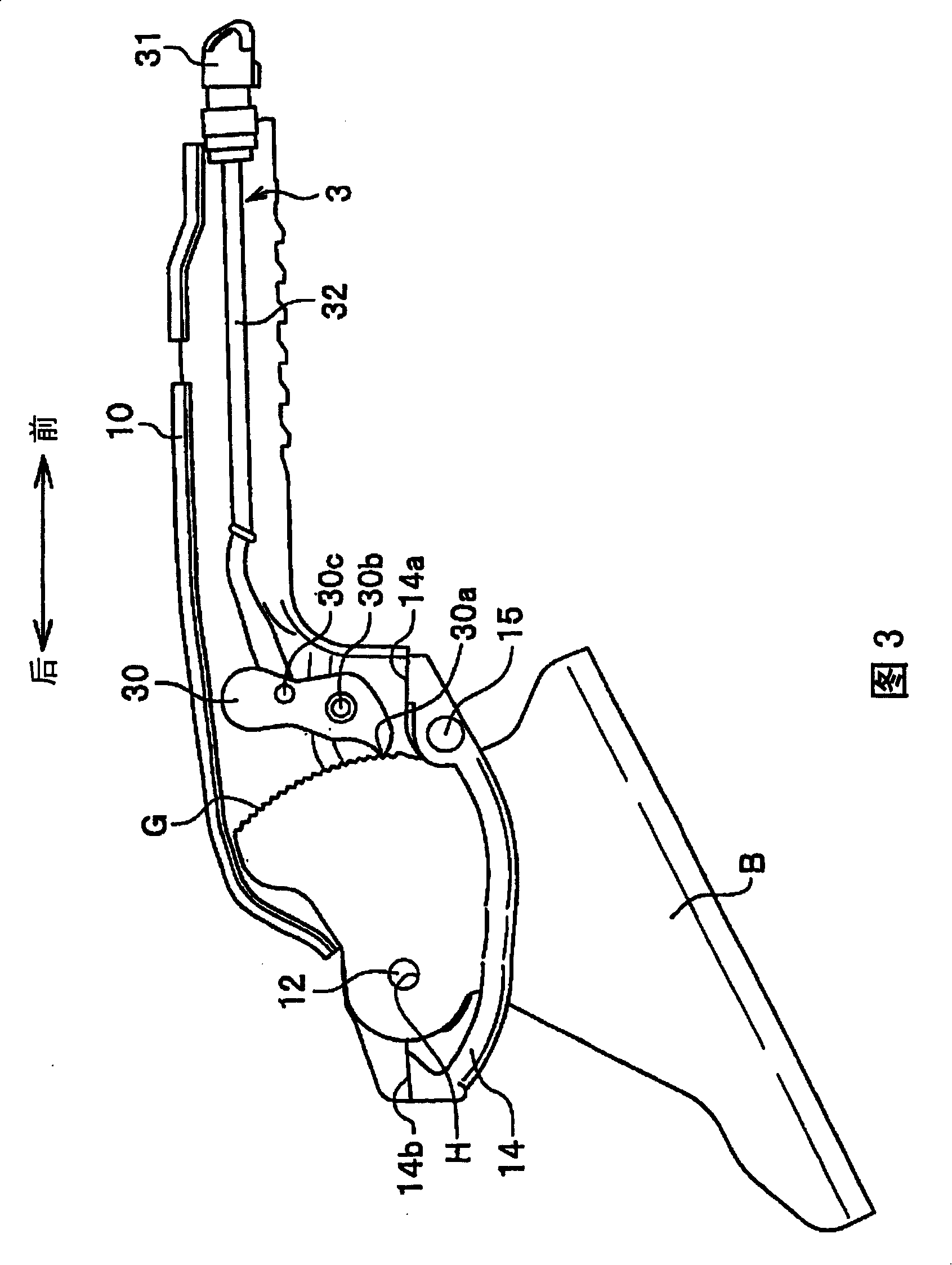
[0018] FIG. 1 is an exploded perspective view showing a parking brake device according to this embodiment, figure 2 It is a perspective view showing an assembled state of the parking brake device according to this embodiment, and FIG. 3 is a plan view showing a lock mechanism unit combined with one side lever member, Figure 4 yes figure 2 A view in direction A, Figure 5 yes figure 2 C-C section view.

[0019] As shown in FIG. 1 , the parking brake device 1 of the present embodiment includes: a board B mounted on a vehicle body (not shown), and a lever 2 (see figure 2 ), locking mechanism part 3, wire 4.

[0020] The base board B is formed in a substantially triangular shape from a metal plate such as iron, and a ratchet G of a predetermined shape is formed on the front peripheral surface, and a circle penetrating the metal plate from one side to the other side is formed behind the ratchet G. Shaped rotating hole H.

[0021] The joystick 2 is composed of a rod membe...


PUM


Abstract

A lever 2 includes first and second lever members 10, 20 between which both sides of a base B are interposed. A guide piece 14 , which is a part of first lever member 10 arranged on first side of the base B, is formed being located on a second side of the base B. The guide piece 14 , which is a part of the first lever member 10 located on the second side, has a guide portion to guide a wire 4 together with a guide piece 24 formed in the second lever member 20.

Description

technical field [0001] The present invention relates to a parking brake device in which a guide portion for guiding a wire is provided on a joystick for manual operation. Background technique [0002] The parking brake device is, for example, installed near the driver's seat of the vehicle. When parking, manually operate the joystick and stretch the wire connecting the joystick and the brake device to make the brake device work, thereby generating a braking force on the vehicle. . For example, Patent Document 1 proposes a parking brake device provided with a guide portion for guiding a wire. Also, if Image 6 As shown, there is proposed a parking brake device 50 in which a guide member 53 is fixed to a lever 52 mounted on a base plate 51 and the tip of a wire 54 is supported by the guide member 53 and the lever 52 . [0003] Patent Document 1: Japanese Unexamined Patent Publication No. 10-287219 (paragraph 0027, FIG. 1 ) [0004] However, in any of the existing parking br...

Claims


Application Information

Patent Timeline
Patent Type & Authority Applications(China)
IPC IPC(8): B60T7/10
CPCB60T7/105Y10T74/20732Y10T74/20582Y10T74/20612Y10T74/2042Y10T74/20438
Inventor 河野英治涉井直人山中史景
Owner HONDA MOTOR CO LTD
Features
  • Generate Ideas
  • Intellectual Property
  • Life Sciences
  • Materials
  • Tech Scout
  • Unparalleled Data Quality
  • Higher Quality Content
  • 60% Fewer Hallucinations
Learn More