High pressure sealing apparatus

A technology for high-pressure sealing and sealing components, applied in sealing, engine sealing, packaging, etc., can solve the problems of large number of parts, large manpower, difficult production and assembly of sealing components, etc.

Inactive Publication Date: 2008-06-11
安藤成雄 +2
View PDF3 Cites 7 Cited by
  • Summary
  • Abstract
  • Description
  • Claims
  • Application Information

AI Technical Summary

Problems solved by technology

Therefore, the number of parts is large and the structure of the sealing assembly is complicated
Therefore, it is not easy to produce and assemble the seal assembly, and also requires a lot of manpower

Method used


Image

  • High pressure sealing apparatus
  • High pressure sealing apparatus
  • High pressure sealing apparatus

Examples


no. 1 approach

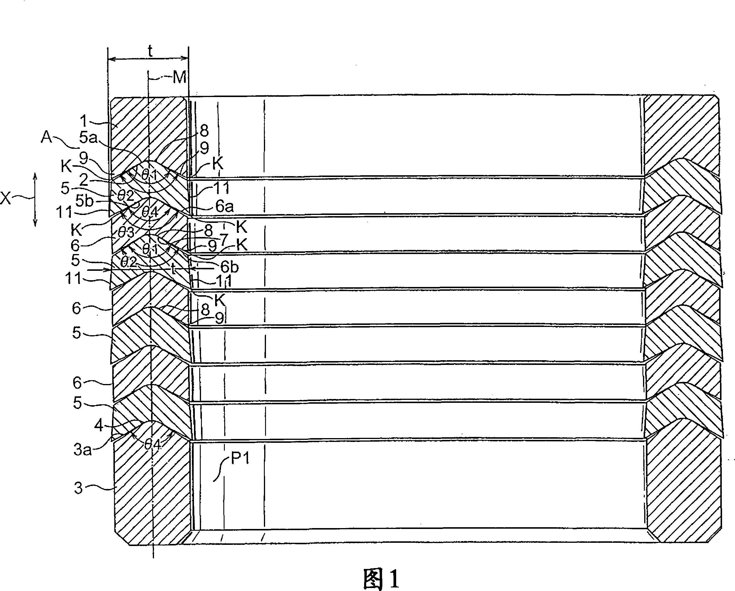
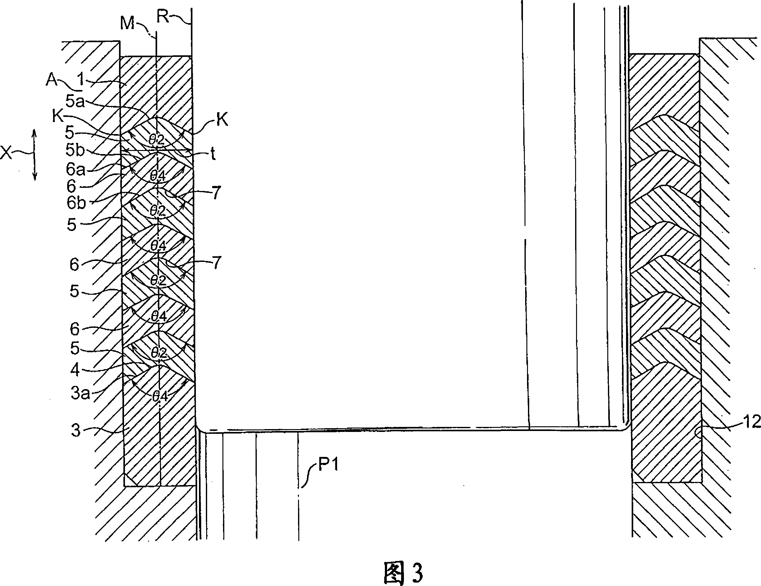
[0051] A first embodiment of a high pressure sealing device according to the present invention will be described with reference to FIGS. 1 to 5 .

[0052] As shown in FIGS. 1 to 5 , the sealing device according to the first embodiment includes:

[0053] a top engaging member 1 having a substantially annular shape in plan view and comprising a seal receiving recess 2 having an inverted V-shaped cross-section at the bottom wall of the top engaging member 1;

[0054] a bottom engagement member 3 having a substantially annular shape in plan view and comprising a seal support wall 4 having an inverted V-shaped cross-section at the top wall of the bottom engagement member 3;

[0055] A plurality of sealing members 5 each having a substantially annular shape in plan view and having an inverted V-shaped cross-section, and the sealing members 5 are interposed between the top joint 1 and the bottom joint 3; and

[0056] A plurality of metal seal support rings 6, each metal seal support...

no. 2 approach

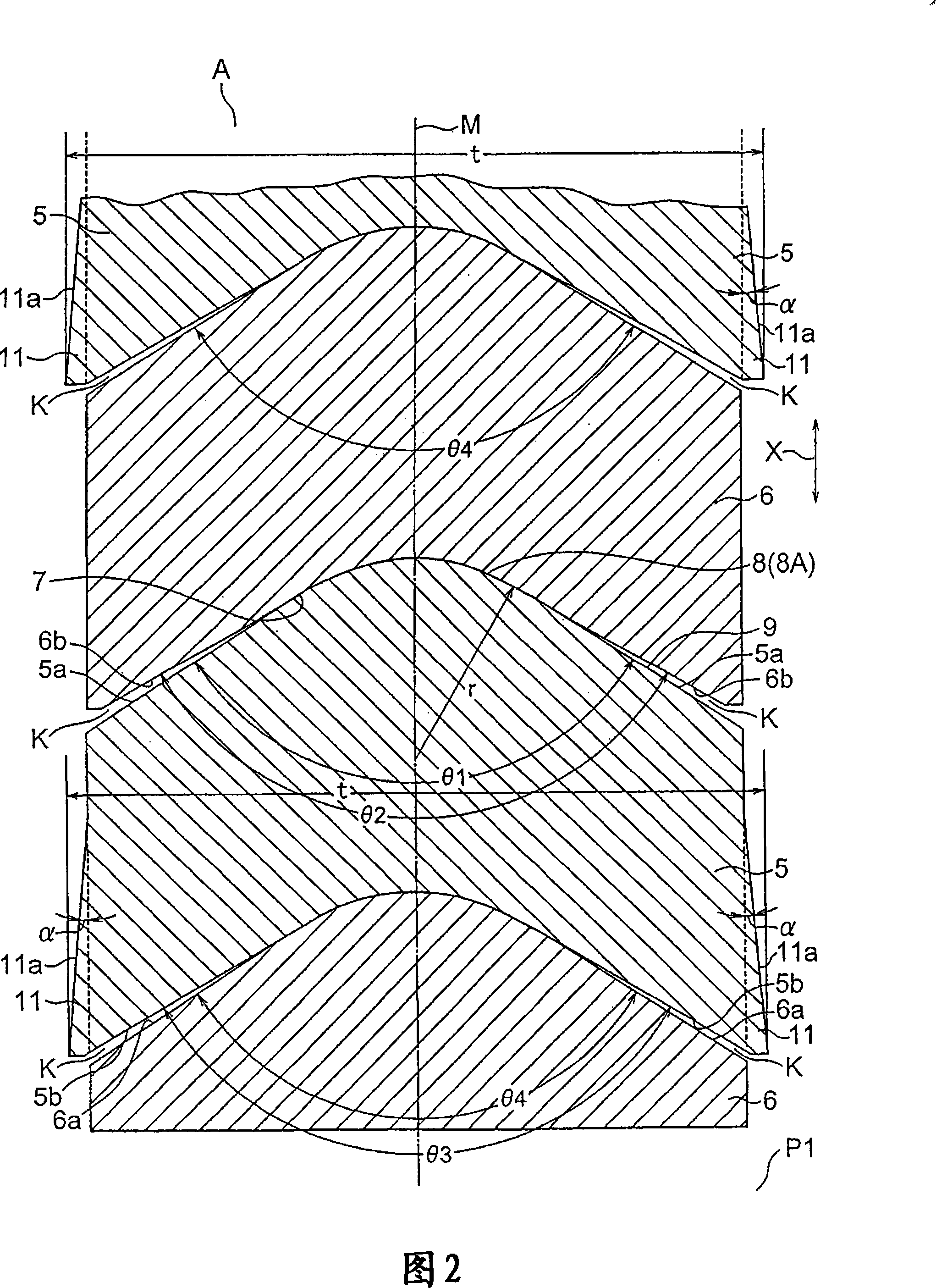
[0079] A second embodiment of the high-pressure sealing device according to the present invention will be described with reference to FIGS. 6 to 9 .

[0080] In the second embodiment, deformation allows the gap K to be formed at the bottom wall 5 b of the sealing member 5 . In the first embodiment, when the pressing force is released, the deformation allowing gap K is formed at both the top wall 5 a and the bottom wall 5 b of the sealing member 5 . In the second embodiment, the inclination angle θ1 formed on the top wall 5a of the sealing member 5 is substantially the same as the inclination angle θ'2 formed on the bottom wall of the top joint member 1 and the inclination angle θ'2 formed on the seal support ring 6. The inclination angle θ'2 of the seal receiving portion 7 on the bottom wall 6b is equal. In addition, the inclination angle θ3 formed on the bottom wall 5b of the seal member 5 is larger than the inclination angle θ4 of the top wall 6a of the seal support ring 6 ...

no. 3 approach

[0084] 10 and 13 show a third embodiment of the sealing device according to the invention.

[0085] In the third embodiment, unlike the first embodiment, a deformation-allowing gap K is formed on the top wall 5 a of the sealing member 5 . That is, in the third embodiment, the inclination angle θ1 formed on the top wall 5 a of the seal member 5 is smaller than the inclination angle θ2 of the seal receiving recess 2 formed on the bottom wall of the top joint 1 , and smaller than the inclination angle θ2 formed on the seal support ring 6 . The inclination angle θ2 of the seal receiving portion 7 on the bottom wall 6b of the . In addition, the inclination angle θ3 formed on the bottom wall 5b of the sealing member 5 is substantially equal to the inclination angle θ4 of the top wall 6a of the seal support ring 6 and the inclination angle θ4 of the top wall of the bottom engaging member 3 . The deformation formed at the top wall 5 a of the seal member 5 allows the gap K to widen as...


PUM

PropertyMeasurementUnit
thermal resistanceaaaaaaaaaa

Abstract

There is provided a high pressure sealing apparatus including: a top adapter including a packing receiving recess having an inverted V-shaped section; a bottom adapter including a packing supporting wall having an inverted V-shaped section; packing members each having an inverted V-shaped section, and interposed between the top adapter and the bottom adapter; and backup rings each having an inverted V-shaped section, and alternately overlapped with the packing members. The packing members are made of hard synthetic resin. A deformation allowing gap is formed on at least two facing walls of a top wall or a bottom wall of the packing member, and a bottom wall of the top adapter, a top wall and a bottom wall of the backup ring, or a top wall of the bottom adapter to be closed owing to compaction force in an axial direction X.

Description

[0001] Cross References to Related Applications [0002] This application is based on Japanese Patent Application No. 2007-175220, the contents of which are hereby incorporated by reference. technical field [0003] The invention relates to a high-pressure sealing device, for example for use in high-pressure homogenizers for processing and cutting up materials contained in suspensions under high pressure, or for example again in high-pressure In the pump, the high-pressure sealing device is used to prevent excessive deformation of the sealing member relative to the sliding rod or the sliding piston, and has good follow-up ability and good sealing ability under high pressure by tightly contacting the rod and the piston with an appropriate contact force, In addition, it has good wear resistance with little deterioration, and has high strength and high heat resistance. Background technique [0004] Typically, there are, for example, seal assemblies for machines such as pumps w...

Claims


Application Information

Patent Timeline
Patent Type & Authority Applications(China)
IPC IPC(8): F16J15/18F16J15/00C08L77/00C08L71/00C08L23/06C08L25/06C08L27/06
CPCF16J15/121F16J15/128Y10S277/944
Inventor 安藤成雄安藤正雄安藤丰禄
Owner 安藤成雄
Why Eureka
Try Eureka