

Method for removing water in the air and thermal regeneration mechanism of dehumidification runner
A heating regeneration and heating mechanism technology, which is applied in the field of dehumidification wheel heating regeneration mechanism to remove moisture in the air, can solve the problems of large heat loss, waste of energy, low thermal efficiency, etc., and achieve the effect of avoiding heat loss and reducing energy consumption
- Summary
- Abstract
- Description
- Claims
- Application Information
AI Technical Summary
Problems solved by technology
Method used
Image

Examples
no. 1 approach 〕
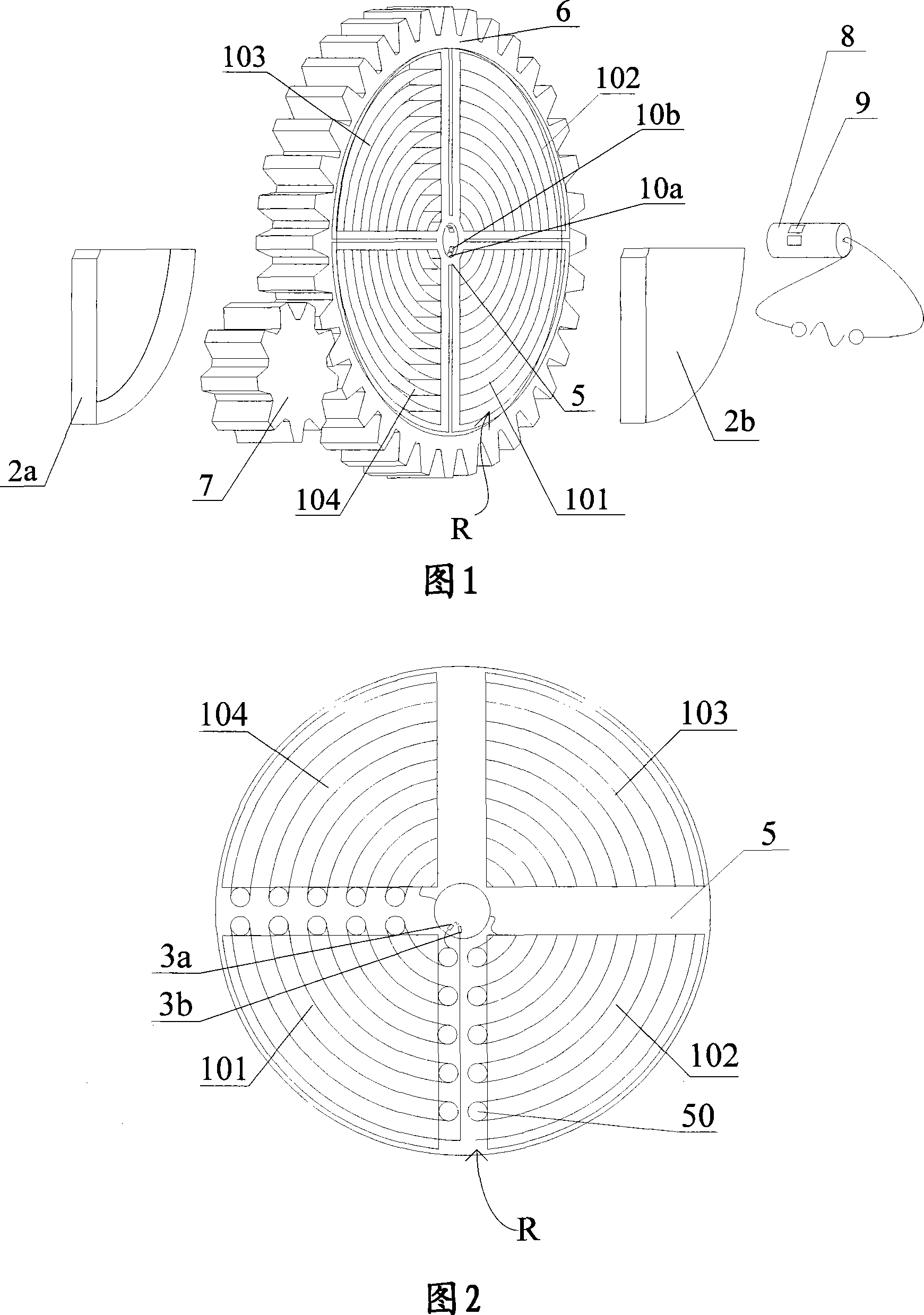
[0026] Fig. 1 is a perspective view showing a desiccant rotor heating regeneration mechanism according to a first embodiment of the present invention. As shown in Figure 1, the desiccant rotor heating regeneration mechanism of this embodiment includes: a desiccant rotor R, a desiccant carrier coated with a hygroscopic agent is arranged in the desiccant rotor R; the desiccant rotor is partially covered from both sides R and a shielding cover 2 defining a shielding area thereon; a step-by-step driving mechanism that rotates the dehumidification wheel R at a specified angle; and heating the moisture in the moisture absorbent in the shielding area to evaporate the water , a heating mechanism that regenerates the moisture absorbent.
[0027] Next, each of the above components will be described in detail.
[0028] 【Dehumidification wheel R】
[0029] As shown in FIG. 1 , the dehumidification wheel R is cylindrical as a whole, including a support frame 5 and a fixed shaft 8 arranged...
no. 2 approach 〕
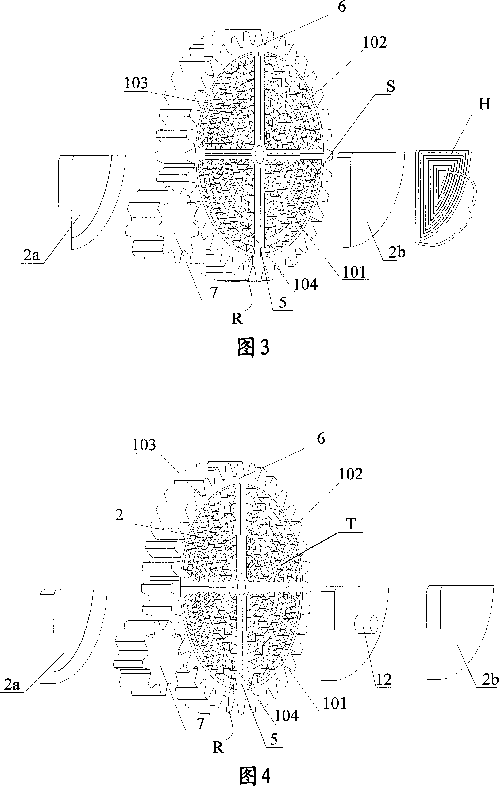
[0051] Fig. 3 is a perspective view showing a desiccant rotor heating regeneration mechanism according to a second embodiment of the present invention. As shown in the figure, this embodiment is an example modified from the first embodiment described above. As far as this embodiment is concerned, the support frame 5 on the dehumidification wheel R (its structure is basically the same as the above-mentioned embodiment, so for the convenience of explanation, the same symbols as the above-mentioned embodiment) and the shielding cover 2. The stepping driving mechanism is the same as that of the first embodiment, therefore, in FIG. 3 , the above three parts are marked with the same symbols. In addition, description of the same parts is omitted in this embodiment. Here, since the support frame 5 is the same as the support frame in the first embodiment, the dehumidification wheel R is also the same as the first embodiment, and is divided into four sectors 101, 102, 103, 104, and Th...
no. 3 approach 〕
[0060] Fig. 4 is a perspective view showing a desiccant rotor heating regeneration mechanism according to a third embodiment of the present invention. This embodiment is a modified example in which the heating mechanism is modified from the second embodiment. In this embodiment, only the heating part is modified, and other parts are the same as those of the above-mentioned second embodiment. Therefore, in the description of this embodiment, the description of parts other than the heating part will be omitted.
[0061] As shown in Figure 4, the difference between the heating part of this embodiment and the above-mentioned second embodiment is that a hygroscopic regenerated net T made of heat-resistant non-metallic material and coated with a hygroscopic agent is installed in the fan-shaped area. The metal mesh S in the above-mentioned second embodiment, and the magnetron 12 provided between the dehumidification wheel R and the shielding cover 2b. In addition, in this embodiment...
PUM
 Abstract
Description
Claims
Application Information