LED control circuit

A control circuit and controller technology, which is applied in the direction of electric lamp circuit layout, electric light source, electrical components, etc., can solve problems such as inconvenient operation, and achieve the effect of eliminating manual operation

Inactive Publication Date: 2008-06-11
HONG FU JIN PRECISION IND (SHENZHEN) CO LTD +1
View PDF0 Cites 32 Cited by
  • Summary
  • Abstract
  • Description
  • Claims
  • Application Information

AI Technical Summary

Problems solved by technology

But at present, almost all LCD displays are manually adjusted the brightness of the backlight source, which is inconvenient to operate

Method used


Image

  • LED control circuit
  • LED control circuit

Examples


Embodiment Construction

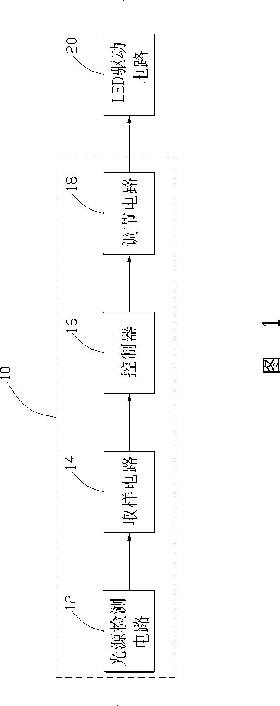
[0012] Referring to FIG. 1 , an LED control circuit 10 includes a light source detection circuit 12, a sampling circuit 14, a controller 16 and an adjustment circuit 18. The light source detection circuit 12 detects the intensity of light in the external environment and generates a Voltage signal, the sampling circuit 14 generates a control signal after sampling the voltage signal, the controller 16 generates a selection signal according to the received control signal, the adjustment circuit 18 is connected to an LED drive circuit 20, and Selectively adjust the working current of the LED driving circuit 20 according to the selection signal.

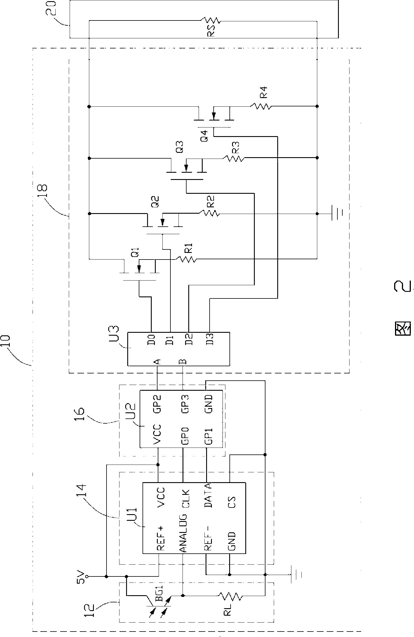
[0013] Continuing to refer to FIG. 2 , the light source detection circuit 12 includes a phototransistor BG1 and a voltage dividing resistor RL, and the phototransistor BG1 and the voltage dividing resistor RL are connected in series between a 5V power supply and ground. The phototransistor BG1 is turned on after receiving light, so that a...


PUM


Abstract

The invention relates to an LED control circuit, which comprises a light source detecting circuit, a sample circuit, a controller and an adjusting circuit. The light source detecting circuit detects the illumination intensity of an outer environment and accordingly generates a voltage signal. The sample circuit samples the voltage signal and generates a control signal. The controller generates a selection signal according to the received control signal. The adjusting circuit is connected with an LED driving circuit and selectively adjusts the working current of the LED driving circuit according to the selection signal. The LED control circuit can automatically change the backlight illumination corresponding to the illumination environment, thus enhancing using life-span of LED.

Description

technical field [0001] The invention relates to a backlight source control circuit, in particular to an LED (light emitting diode) control circuit. Background technique [0002] Liquid crystal displays (LCDs) are widely used in fields such as notebook computers, handheld computers (PDAs) and mobile phones due to their light weight and small size, and have gradually replaced traditional CRT displays and TVs. However, the LCD is not a self-luminous display, but a light-receiving display for receiving light to form an image, so that the user cannot distinguish the image in a dark environment. To solve this problem, a backlight module is installed on the rear surface of the LCD. LCD provides display light source. [0003] According to the way the light source produces images, LCDs can be divided into two types: reflective and transmissive. Early LCDs were mostly reflective, but currently transmissive LCDs dominate the market. The transmissive LCD is divided into side-edge and ...

Claims


Application Information

Patent Timeline
Patent Type & Authority Applications(China)
IPC IPC(8): G09G3/34G09G3/36G09G3/20G09G5/10G02F1/133G02F1/13357H05B37/02G02F1/1335
CPCG09G3/3406G09G2360/144H05B33/0854G09G2320/0633H05B45/12
Inventor 陈晓竹陈明科
Owner HONG FU JIN PRECISION IND (SHENZHEN) CO LTD
Why Eureka
Try Eureka