Optical pickup device, reproducing device and birefringence correction plate

An optical pickup and birefringence technology, which is applied in beam guiding devices, optical recording/reproduction, instruments, etc., can solve the problem of increased birefringence variation, greater influence, and greater influence of transparent substrates, etc. question

Inactive Publication Date: 2008-06-11
HITACHT MAXELL LTD
View PDF2 Cites 1 Cited by
  • Summary
  • Abstract
  • Description
  • Claims
  • Application Information

AI Technical Summary

Problems solved by technology

[0014] As a result of examining the influence of birefringence on HD DVD, the inventors of the present invention found that, in the case of HDDVD standard, although the laser wavelength was shortened and the numerical aperture was increased (0.60→0.65), the areal density was improved. But on the contrary, the light transmission properties of the information recording medium existing between the information recording surface of the information recording medium and the objective lens of the optical pickup device, that is, the influence of the birefringence of the transparent substrate becomes larger, and the degree of signal modulation is relatively larger than that of the transparent substrate. The fluctuation of the fluctuation of in-plane birefringence increases
That is, it is known that for HD DVD, the influence of birefringence of the transparent substrate becomes larger, and the allowable range of in-plane birefringence (relative to the range of variation of in-plane birefringence) becomes narrower.

Method used


Image

  • Optical pickup device, reproducing device and birefringence correction plate
  • Optical pickup device, reproducing device and birefringence correction plate
  • Optical pickup device, reproducing device and birefringence correction plate

Examples


Embodiment 1

[0102] First, the optical pickup device will be described.

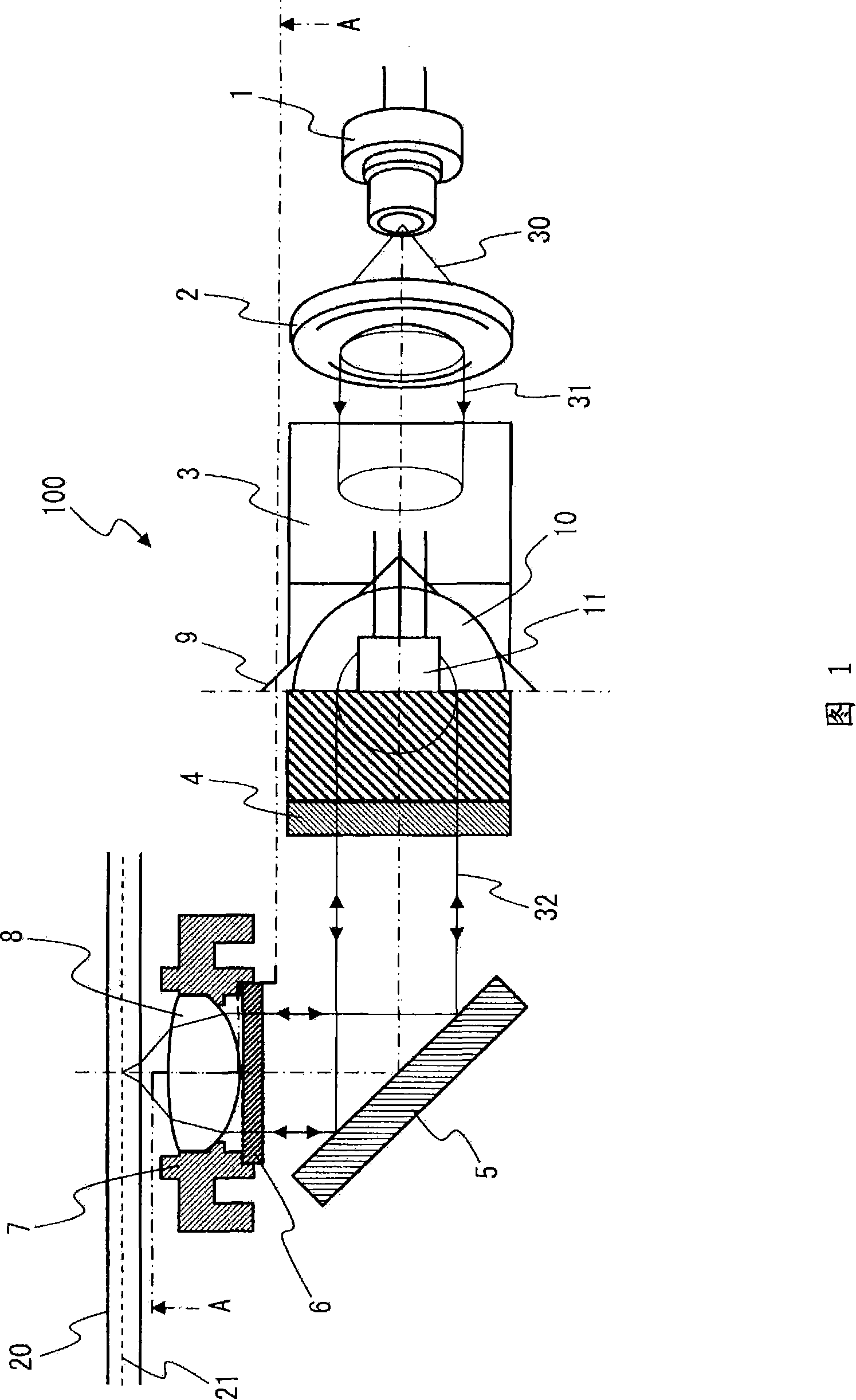
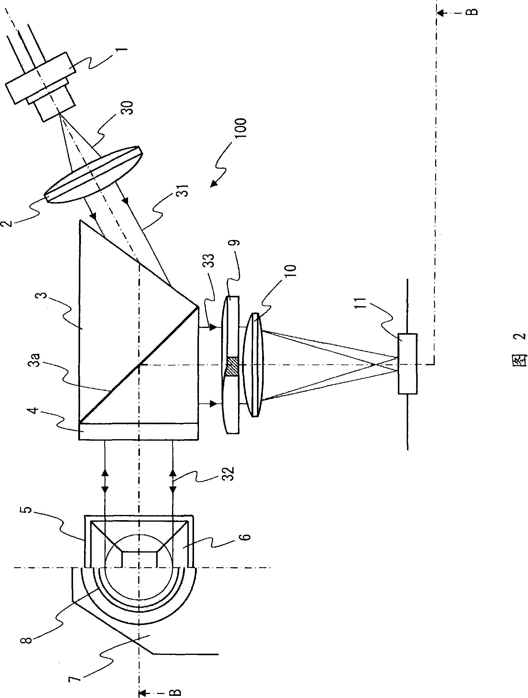
[0103] Fig. 1 and Fig. 2 show the schematic structure of the optical pickup device of the first embodiment. In addition, FIG. 1 is a diagram showing the B-B cross section in FIG. 2, and FIG. 2 is a diagram showing the A-A cross section in FIG. 1.

[0104] The optical pickup device 100 of Embodiment 1 is shown in Figs. 1 and 2, and is mainly composed of the following components: a semiconductor laser 1 (light source) that emits a light beam with a wavelength of 405 nm; a collimator lens 2; a compound prism 3 (polarization beam splitter) ); λ / 4 plate 4; upright lens 5; birefringence compensation plate 6; objective lens 8; lens holder 7 holding the objective lens; cylindrical lens 9; condenser lens 10 and light detector 11. In this example, as shown in FIG. 1, the birefringence compensation plate 6 is arranged on the optical path between the compound prism 3 and the objective lens 8 and is supported by the lens holder 7. In...

Embodiment 2

[0140] First, the optical pickup device will be described.

[0141] 17 and 18 show the schematic structure of the optical pickup device of the second embodiment. In addition, FIG. 17 is a diagram showing a B'-B' cross-section in FIG. 18, and FIG. 18 is a diagram showing a A'-A' cross-section in FIG.

[0142] The optical pickup device 200 of the second embodiment is shown in Figs. 17 and 18, and is mainly composed of the following components: a semiconductor laser 1 (light source) emitting a light beam with a wavelength of 405 nm; a collimator lens 2; a compound prism 3 (polarization beam splitter) ); λ / 4 plate 4; stand up mirror 5; birefringence compensation plate 6'; objective lens 8; lens holder 7 holding the objective lens; cylindrical lens 9; condenser lens 10 and light detector 11. In this example, the birefringence compensation plate 6'is arranged on the optical path between the objective lens 8 and the disc-shaped information recording medium 20 as shown in Fig. 17 and is s...


PUM

PropertyMeasurementUnit
Wavelengthaaaaaaaaaa
Thicknessaaaaaaaaaa

Abstract

An optical pickup device is provided with a light source; an objective lens for focusing an optical beam emitted from the light source on a recording plane; a polarizing beam splitter arranged on an optical path between the light source and the objective lens; and a birefringence correction plate arranged on an optical path between the objective lens and the polarizing beam splitter for giving a phase difference between two polarization components of the entered optical beam which are orthogonally intersecting each other. In the optical pickup device, the phase difference generated by the birefringence correction plate differs, depending on a position within the plane of the birefringence correction plate. Thus, influence of birefringence is more effectively reduced by using the simpler optical element, and a margin for birefringence fluctuation of an information recording medium is widened.

Description

Technical field [0001] The present invention relates to an optical pickup device that irradiates light on a recording surface of an information recording medium having a light-transmitting medium and receives reflected light from the recording surface, a playback device, and birefringence compensation used in these devices board. Background technique [0002] In the field of information recording media technology, the improvement of recording density has become an increasingly important technical issue. In the past, recording was achieved from two aspects: improvement of recording media along the line of information channels and improvement of surface recording density by narrowing the channel pitch. Increase in density. [0003] With regard to DVD, which is one of the information recording media, by setting the laser wavelength to 650 nm and setting the numerical aperture NA of the objective lens to 0.6, an areal density of 4.7 GB in CD size can be achieved. In addition, for the...

Claims


Application Information

Patent Timeline
IPC IPC(8): G11B7/135
CPCG11B7/1367G02B19/0028G02B19/0085G02B17/0868
Inventor 杉山寿纪
Owner HITACHT MAXELL LTD
Why Eureka
Try Eureka