Method for adhesively fixing liquid gas adiabatic apparatus by undulance adhesive strip

A thermal insulation device and adhesive strip technology, which is applied to fixed-capacity gas storage tanks, transportation and packaging, and for bulk cargo, can solve the problems of increasing the production cost of shipping liquefied gas tanks, etc.

Active Publication Date: 2008-06-18
GAZTRANSPORT & TECHNIGAZ SA
View PDF3 Cites 10 Cited by
  • Summary
  • Abstract
  • Description
  • Claims
  • Application Information

AI Technical Summary

Problems solved by technology

[0007] [07] Furthermore, the extensive use of adhesive strips has the disadvantage of significantly increasing the production cost of shipping liquefied gas tanks due to the large amount of adhesive required

Method used


Image

  • Method for adhesively fixing liquid gas adiabatic apparatus by undulance adhesive strip
  • Method for adhesively fixing liquid gas adiabatic apparatus by undulance adhesive strip
  • Method for adhesively fixing liquid gas adiabatic apparatus by undulance adhesive strip

Examples


Embodiment Construction

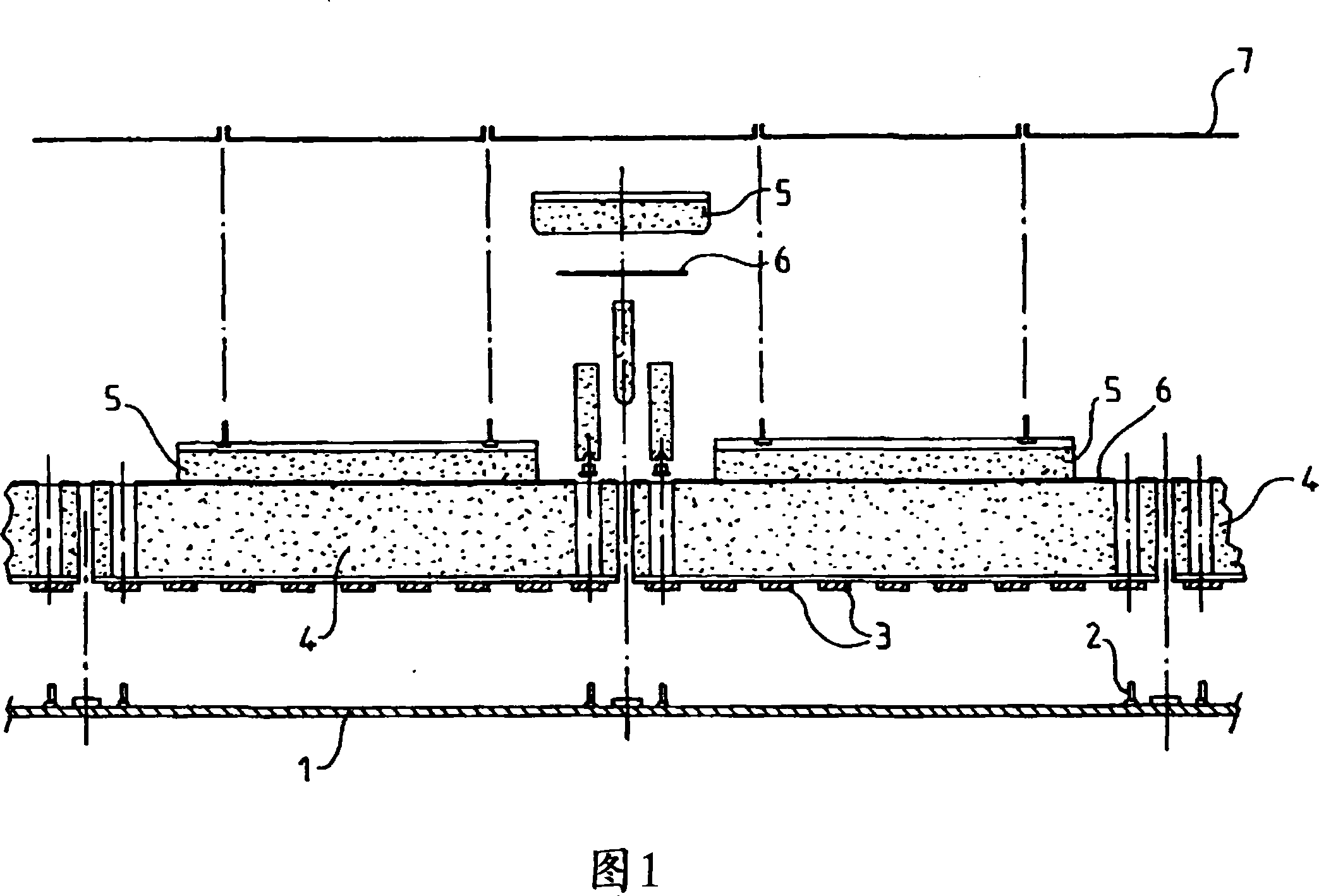
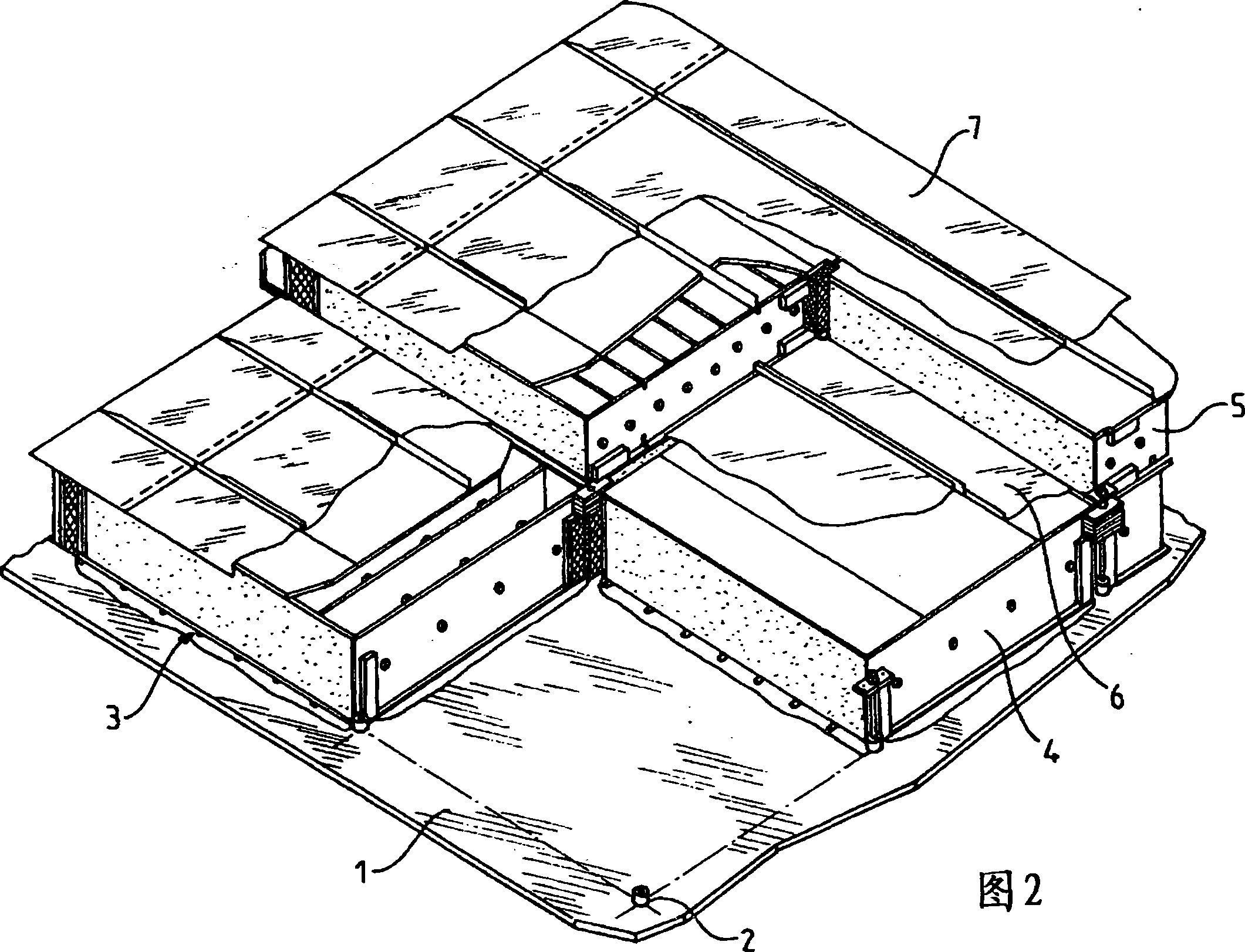
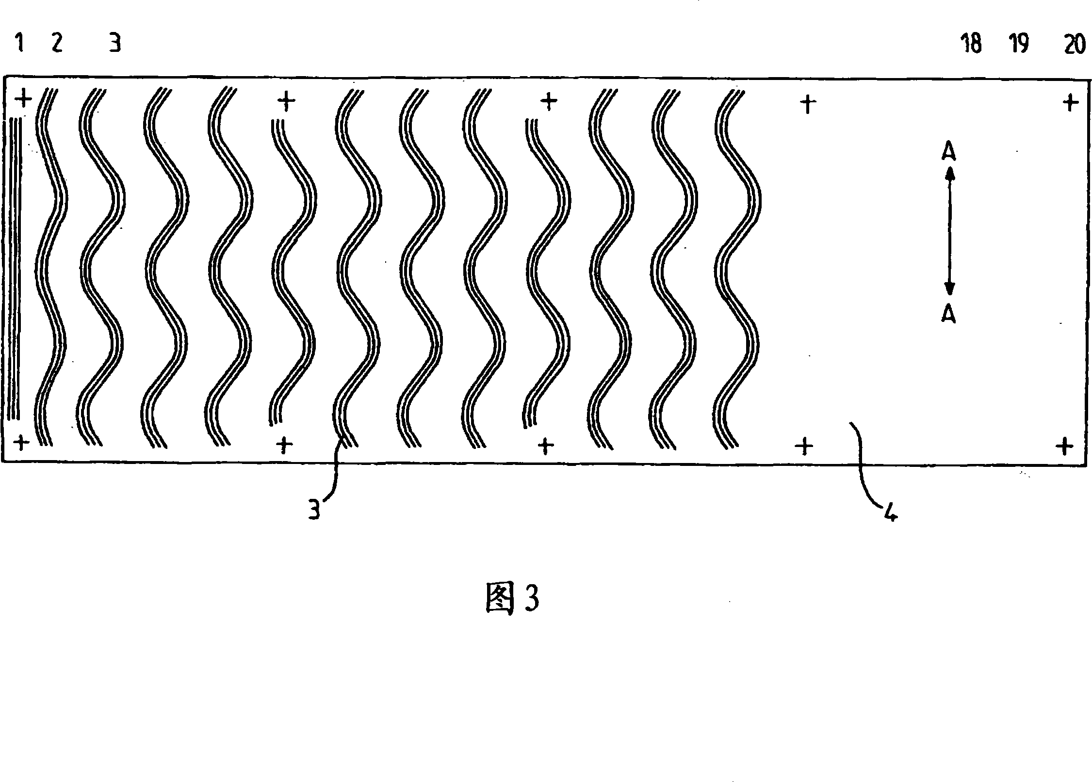
[0022] [22] Referring to Figure 1, it can be seen the inner hull 1 of a ship transporting liquefied gas, to which bolts 2 for holding the second insulation 4 in place during its installation have been secured, these The insulation is made in the form of foam blocks placed on the carrier slats to form a secondary insulation barrier. These second insulating means 4 are fastened to the inner casing 1 by means of adhesive strips 3 which are arranged transversely to the maximum dimension of the second insulating means on the bottom surface of the carrier strips of the insulating means, and the second The heat insulating device 4 is kept in contact with the inner housing 1 during its installation by means of fixing parts cooperating with the bolts 2 . (Note: For the convenience of language description, from now on, regardless of whether the second insulation device is used to be placed on the floor, top surface or side wall of the shell, the bottom surface of the second insulation d...


PUM


Abstract

The method involves arranging adhesive beads (3) on a lower side of a panel of an insulating block (4) along sinuous lines parallel to each other, and arranging the insulating block on an inner body (1) of a ship. The insulating block is pressed against the inner body until polymerization of an adhesive, and the adhesive beads are made of epoxy resin. The adhesive beads are applied on the lower side of the panel of the insulating block along the parallel sinuous lines, where a distance between the successive adhesive beads is equal or greater than 100 millimeter.

Description

technical field [0001] [01] The technical field of the invention relates to the fastening of hermetically sealed tanks to support structures, in particular to the hulls of ships for the marine transport of liquefied gases, in particular for the transport of liquefied natural gas with a high methane content. Background technique [0002] [02] In French patents 2265603, 2798902, 2683786, 2691520 and 2724623, a method of manufacturing a sealed and insulated tank of this type has been described, said tank comprising two continuous sealing barriers connected to two Layers of insulation called insulation barriers are arranged alternately. A first sealing barrier, called the primary sealing barrier, is in contact with the liquefied gas, while a second sealing barrier, called the secondary sealing barrier, is arranged between the two insulating barriers. The individual barriers are secured to each other and the secondary insulation barrier is secured to the inner hull of the ship b...

Claims


Application Information

Patent Timeline
Patent Type & Authority Applications(China)
IPC IPC(8): B63B25/16B63B9/06B29C65/50
CPCF17C2270/0107B63B3/68B63B25/16Y10S220/901F17C3/025B63B25/08
Inventor 雅克·德莱姆热里·康莱
Owner GAZTRANSPORT & TECHNIGAZ SA
Why Eureka
Try Eureka