Gas path pressure release device and corresponding gas path pressure release device realizing large pressure reducing ratio

A decompression device and air circuit technology, which is applied in the direction of valve device, fluid pressure control without auxiliary power, safety valve, etc., can solve the problems of large decompression spring force, difficult decompression spring force, small decompression, etc.

Active Publication Date: 2008-06-18
CAMA LUOYANG GAS SUPPLY
View PDF0 Cites 11 Cited by
  • Summary
  • Abstract
  • Description
  • Claims
  • Application Information

AI Technical Summary

Problems solved by technology

However, the known pressure reducer works under the resultant force of the spring force received by the piston and the force received by the piston. Because the air pressure working pressure is relatively high, the force of the decompression spring is large, and it is difficult to adjust the force of the pressure decompression spring, and the decompression ratio is small.

Method used


Image

  • Gas path pressure release device and corresponding gas path pressure release device realizing large pressure reducing ratio
  • Gas path pressure release device and corresponding gas path pressure release device realizing large pressure reducing ratio

Examples


Embodiment Construction

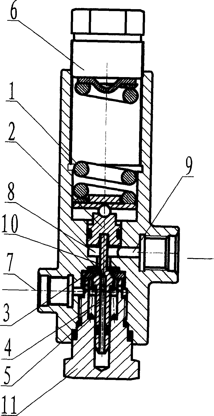
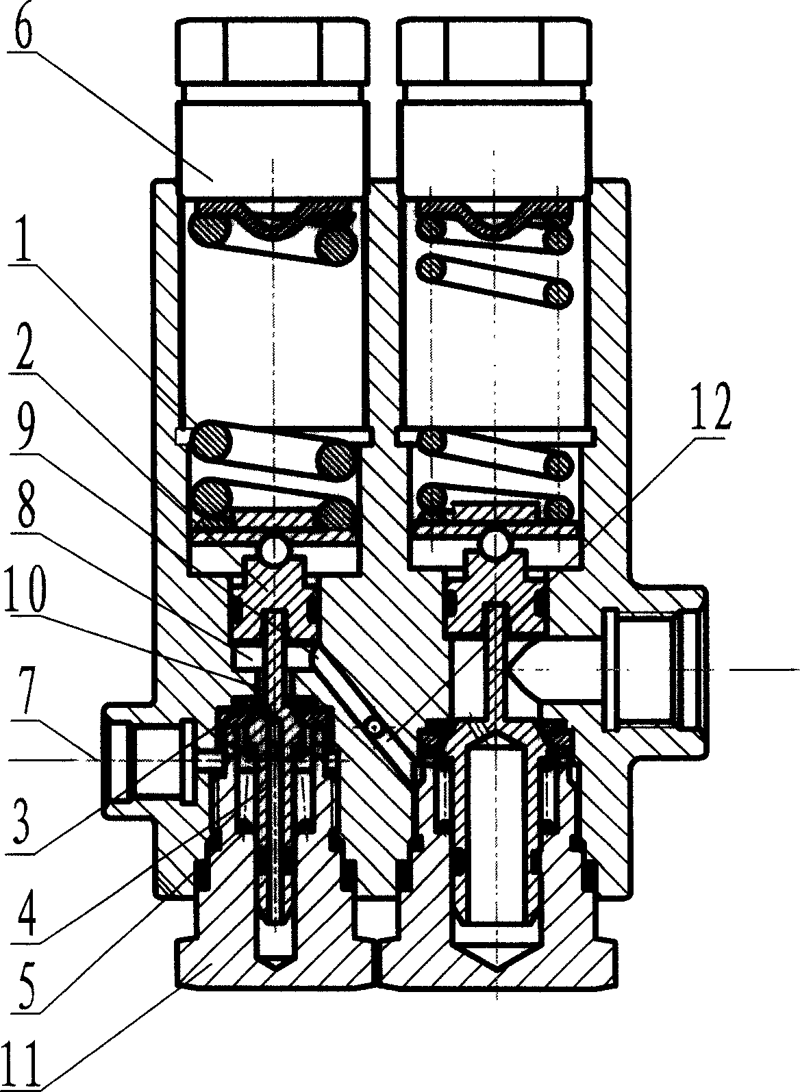
[0015] Such as figure 1 In the air pressure decompression device shown, a piston cavity is arranged in the housing of the decompression device, and a decompression spring chamber and a ejector rod chamber are connected to the coaxial line at both ends of the piston cavity, and a piston 2 is installed in the piston cavity. The compression spring chamber is equipped with a decompression spring 1 that is pressure-fitted with the inner end and the piston 2. The outer end of the decompression spring is press-fitted with a pressure-regulating nut 6 that is helically assembled on the outdoor port of the decompression spring. The axis is equipped with a push rod 4 whose inner end is press-fitted with the piston. The push rod is equipped with a preload spring 5 that drives the push rod to press the piston. The valve seal structure is composed of the dynamic sealing surface and the static seal at the passage 10, the ejector rod chamber is a sealed space, the ejector rod chamber is conne...


PUM


Abstract

The invention relates to an air path relief device. A housing of the relief device is provided with a piston cavity. The two ends of the piston cavity are communicated and provided with a relief spring chamber and a top rod chamber in a same axis. The piston cavity is provided with a piston. The relief spring chamber is provided with a relief spring in top pressure cooperation with the inner end and the piston. The external end of the relief spring is in top pressure cooperation with a pressure regulating screw cap spirally arranged in an external port of the relief spring chamber. An inner axis of the top rod chamber is provided with the top rod the inner end of which is in top pressure cooperation with the piston. The top rod is provided with a top pressure spring driving the top rod to support and press the piston. A valve sealing structure consisting of a dynamic sealing surface covered on the top rod and a static sealing surface arranged at a channel location is arranged on the channels of the top rod chamber and the piston cavity. The top rod chamber which is a sealing space is communicated with an air inlet. The channel between the piston and the sealing structure is communicated and provided with an air distributing cabin. The invention realizes feedback through changing the force way and sealing way of the piston and by using a secondary relief mechanism and has a good stability.

Description

technical field [0001] The invention relates to a gas path decompression device and a corresponding gas path decompression device realizing a large decompression ratio. Background technique [0002] At present, known decompressors are mostly made up of preload spring, decompression spring, piston, push rod, sealing surface, and pressure distribution chamber. The ejector rod and the sealing surface of this kind of pressure reducer are integrated. When the piston is subjected to high air pressure, the piston moves, driving the ejector rod to move, the sealing surface moves away with the ejector rod, the gas passage, the pressure reducer opens, and due to the interception and decompression, The output pressure is lower than the inlet pressure to achieve the decompression effect. But the known pressure reducer works under the resultant force of the spring force and the force that the piston is subjected to, because the air pressure working pressure is higher, the force of the d...

Claims


Application Information

Patent Timeline
Patent Type & Authority Applications(China)
IPC IPC(8): F16K17/04G05D16/10
Inventor 石文星张猛
Owner CAMA LUOYANG GAS SUPPLY
Why Eureka
Try Eureka