Automatically tracking device for elevation rotating shaft fixed solar receiver
A technology of automatic tracking device and elevation angle rotating shaft, which is applied in the direction of solar thermal device, solar thermal power generation, heating device, etc., can solve the problems of high production cost, low collection efficiency, complex structure, etc., and achieve low manufacturing cost, reasonable structure, and tracking accurate effect
- Summary
- Abstract
- Description
- Claims
- Application Information
AI Technical Summary
Problems solved by technology
Method used
Image

Examples
Embodiment Construction
[0013] The present invention is further described below in conjunction with embodiment and accompanying drawing.
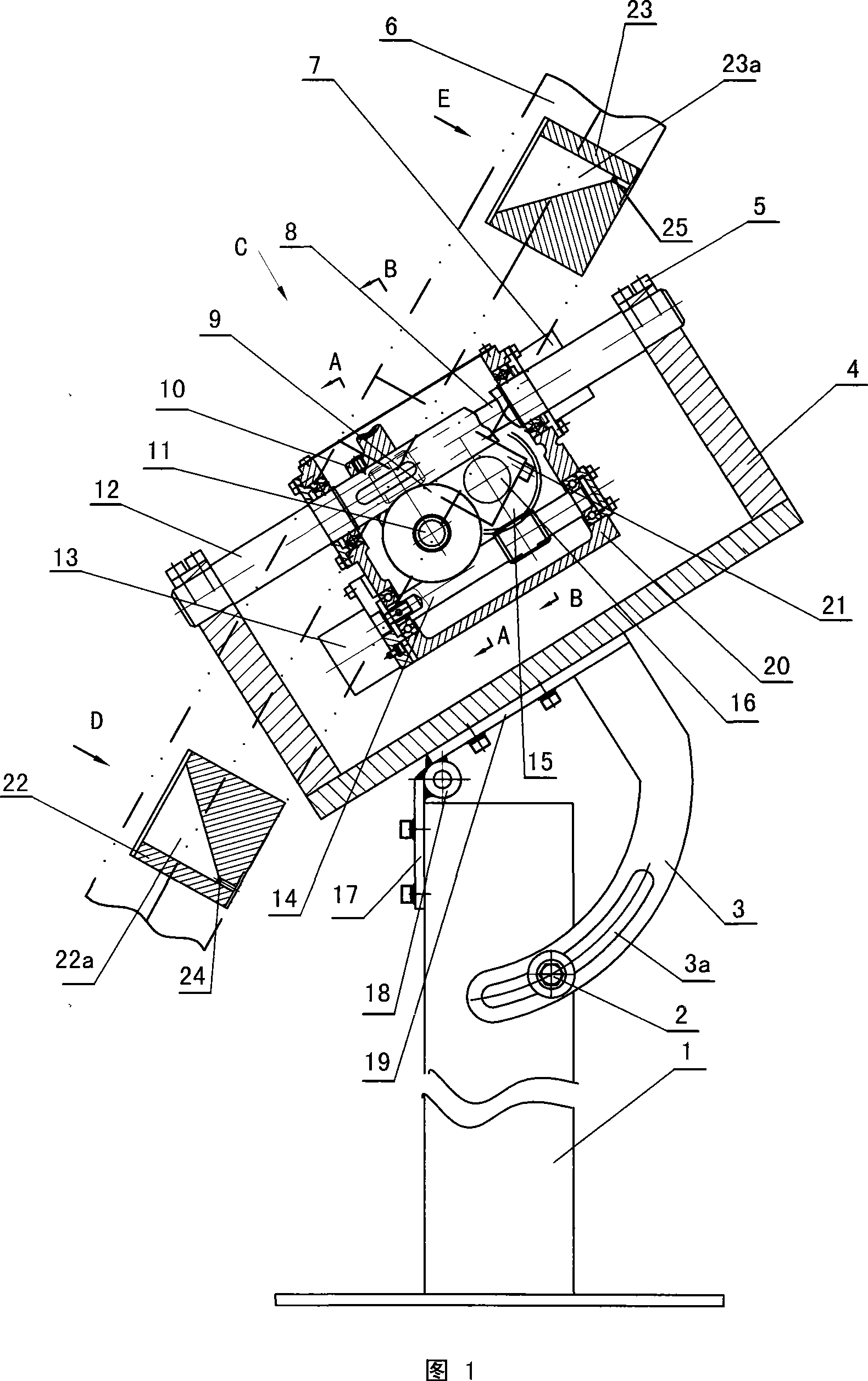
[0014] Referring to Fig. 1, the fixed solar receiver automatic tracking device of the elevation angle rotating shaft provided by the present invention has a base 1, a support 4 is supported on the base 1, a light receiver is connected on the support, and a connection with the earth is fixed on the support 4. The azimuth shaft 12 parallel to the rotation axis is equipped with a casing 20 on the azimuth shaft 12, and the elevation angle rotating shaft 16 perpendicular to the azimuth axis 12 is housed on the casing 20, and the optical receiver 6 is connected with the elevation angle rotating shaft 1 by a support plate 21.
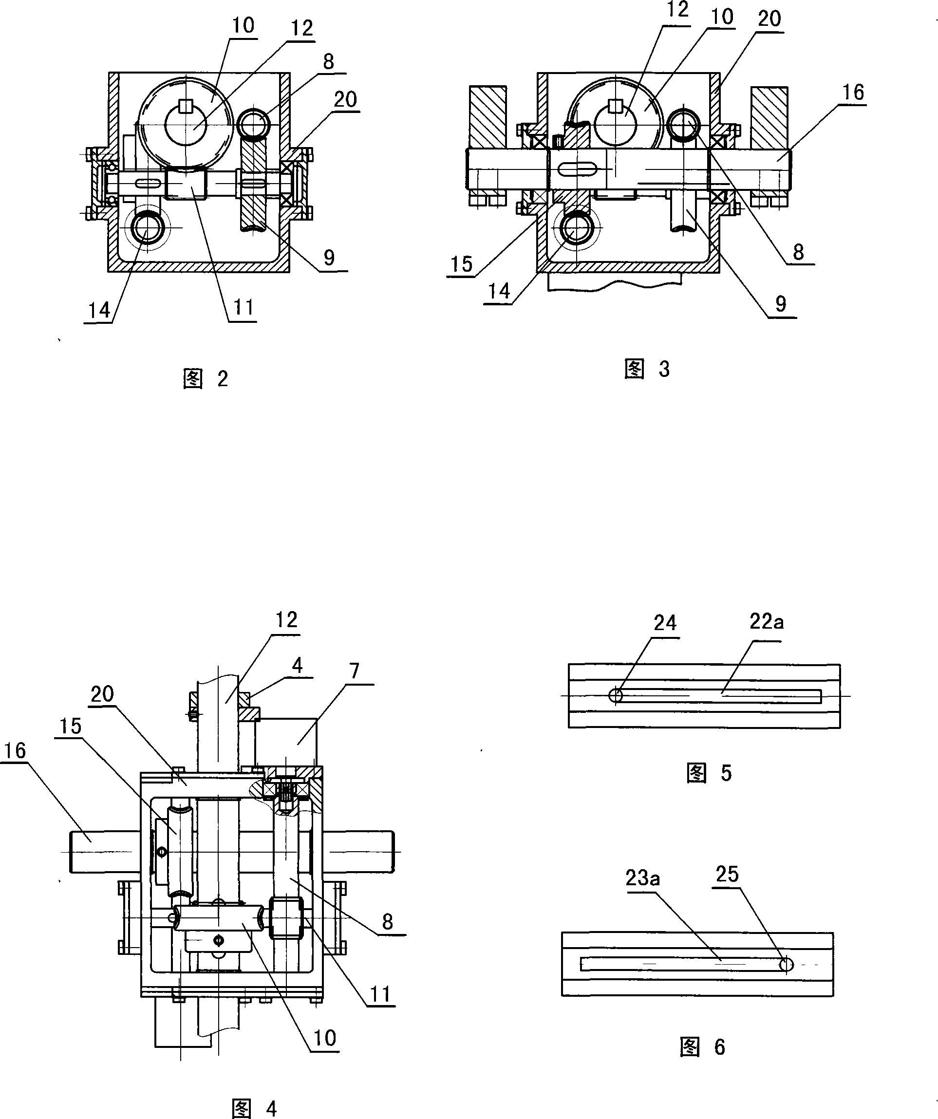
[0015] 1, FIG. 2, FIG. 4, on the box body 20, the azimuth transmission mechanism that the transmission box body 20 rotates around the azimuth axis 12 is formed as follows: a driving worm 8 and a driven worm 11 are mounted on the box body 20 A worm...
PUM
 Abstract
Description
Claims
Application Information
 - Generate Ideas
- Intellectual Property
- Life Sciences
- Materials
- Tech Scout
- Unparalleled Data Quality
- Higher Quality Content
- 60% Fewer Hallucinations
Browse by: Latest US Patents, China's latest patents, Technical Efficacy Thesaurus, Application Domain, Technology Topic, Popular Technical Reports.
© 2025 PatSnap. All rights reserved.Legal|Privacy policy|Modern Slavery Act Transparency Statement|Sitemap|About US| Contact US: help@patsnap.com