

Rfid reader and circuit and method for echo cancellation thereof
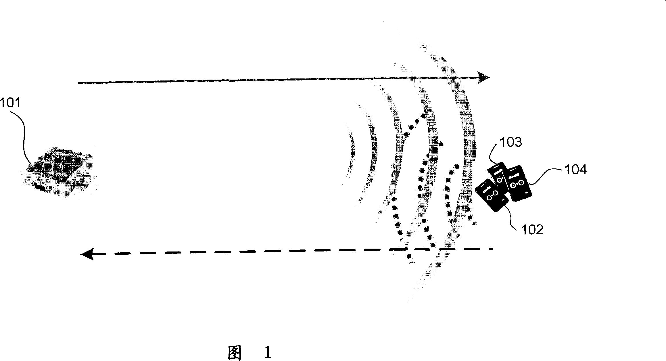
一种射频识别装置、回声消除的技术,应用在内存记录载体读取问题、仪器、电气元件等方向,能够解决减低读取器101灵敏度以及无杂波干扰动态范围等问题
- Summary
- Abstract
- Description
- Claims
- Application Information
AI Technical Summary
Problems solved by technology
Method used
Image

Examples
Embodiment Construction
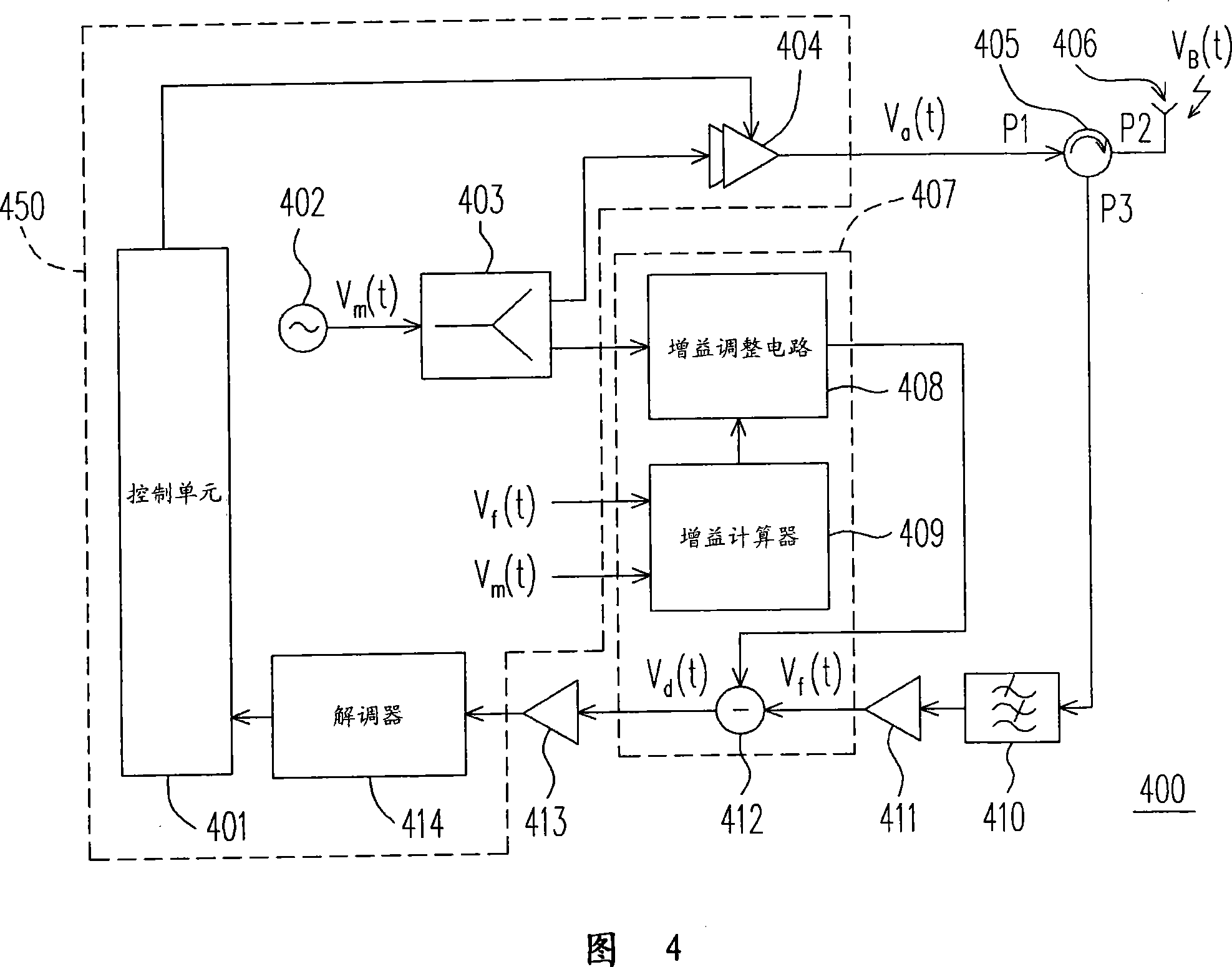
[0070] FIG. 4 shows a schematic circuit diagram of an RFID reader 400 including an echo cancellation circuit 407 according to an embodiment of the present invention. The RFID reader 400 includes a back-end module 450 , a circulator 405 , an antenna 406 , a band-pass filter (BPF: band-pass filter) 410 , two low-noise amplifiers 411 and 413 , and an echo cancellation circuit 407 . The back-end module 450 includes a control unit 401 , a radio frequency oscillator 402 , a power splitter 403 , a power amplifier 404 , and a demodulator 414 . Among the elements of the RFID reader 400, the control unit 401, the RF oscillator 402, the power splitter 403, the circulator 405, the antenna 406, and the demodulator 414 are compatible with the existing RFID reader 101 The corresponding elements in are similar. The power splitter 403 can be replaced by a coupler or any device with the same signal transmission capability. The circulator 405 can be replaced with a coupler or any device with t...
PUM
 Abstract
Description
Claims
Application Information