
Permanent magnetism contactor operation mechanism

An operating mechanism and contactor technology, applied in the direction of electromagnetic relays, electromagnetic relay details, relays, etc., can solve problems such as inability to automatically break

Inactive Publication Date: 2010-08-11
SOUTHEAST UNIV
View PDF2 Cites 0 Cited by
  • Summary
  • Abstract
  • Description
  • Claims
  • Application Information

AI Technical Summary

Problems solved by technology

In particular, it completely solves the problem that the permanent magnet contactor cannot be automatically broken after manual closing

Method used


Image

  • Permanent magnetism contactor operation mechanism
  • Permanent magnetism contactor operation mechanism
  • Permanent magnetism contactor operation mechanism

Examples


Embodiment Construction

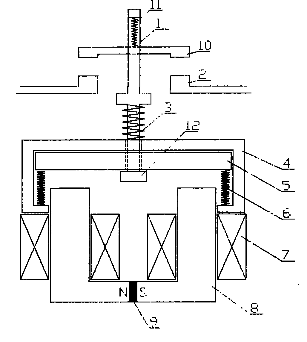
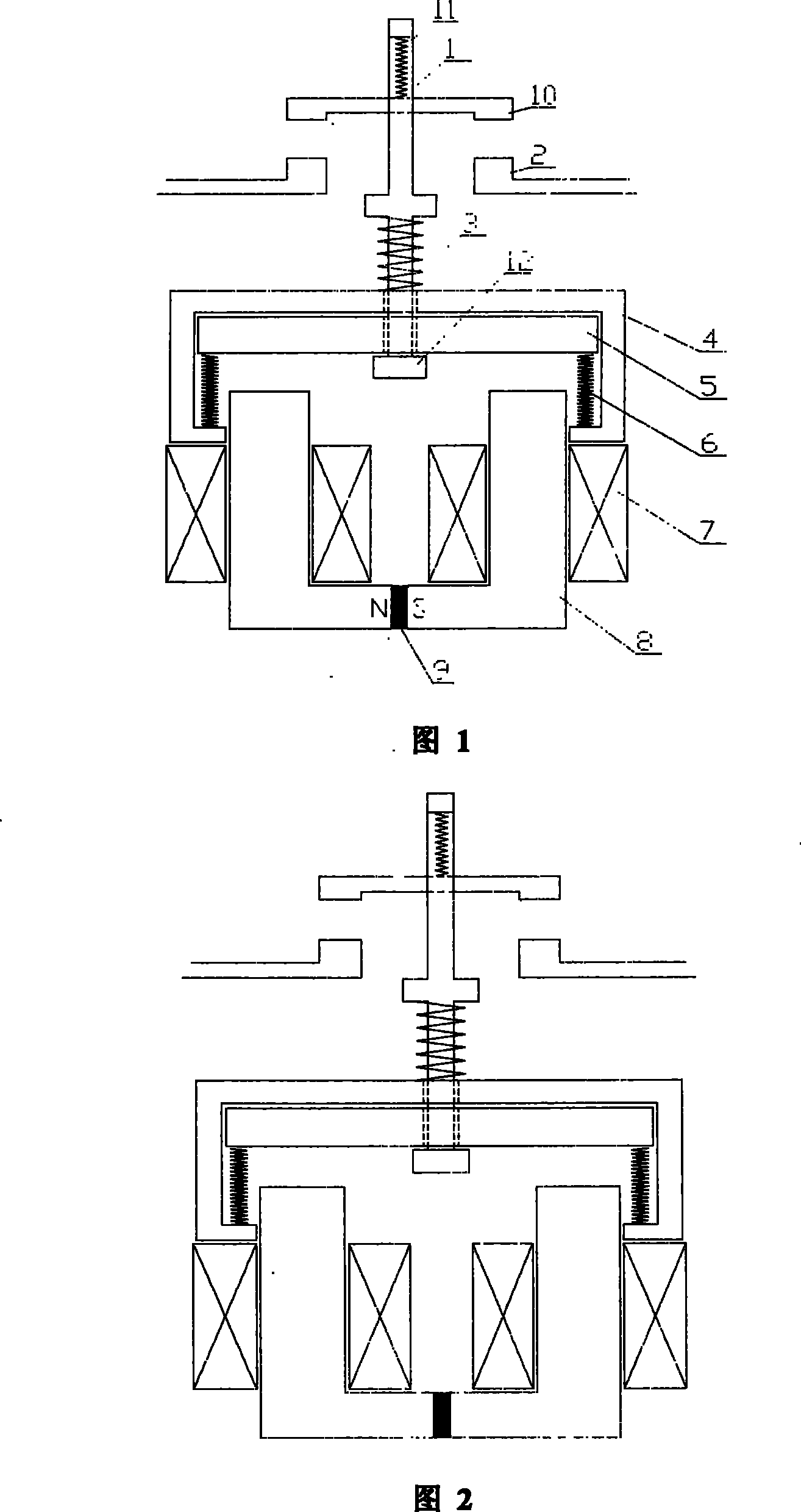
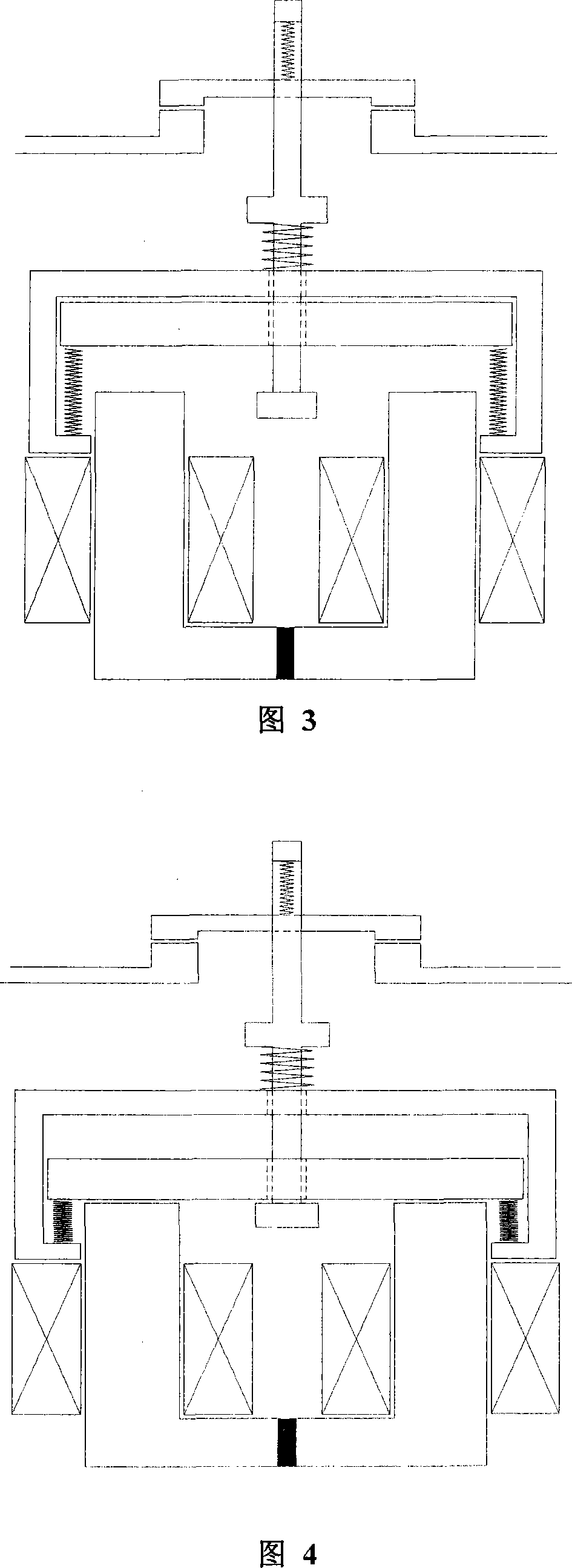
[0024] The U-shaped structure of the permanent magnet contactor operating mechanism of the present invention, as shown in (Fig. 1), mainly consists of a contact drive shaft 1, a static contact 2, a first spring 3, a molded case support 4, and a moving iron core 5 , The second spring 6, the coil 7, the static iron core 8, the permanent magnet 9, the moving contact 10, the contact spring 11, and the support 12 are composed. Its structural features are: a moving iron core 5 is provided at the upper end of the molded case bracket 4, the upper end of the second spring 6 is pushed against the lower part of the moving iron core 5, and the lower end of the second spring 6 is pushed against the lower part of the plastic case bracket 4. The second spring 6 provides the reaction force of the moving iron core 5; the static iron core 8 has two parts, a permanent magnet 9 is arranged between the two parts of the static iron core 8, and a coil 7 is respectively arranged on the two parts of th...


PUM


Abstract

The invention relates to a permanent magnetic contactor operation mechanism. A dynamic iron core (5) is arranged at an inner upper end of a plastic casing bracket (4). The lower part of the dynamic iron core (5) is supported by the upper end of a second spring (6). The inner lower part of the plastic casing bracket (4) is supported by the lower end of the second spring (6). A static iron core (8)is provided with two parts and a permanent magnet (9) is arranged between the two parts. A coil (7) is respectively arranged on the static iron cores (8) of the two parts. Upper parts of the static iron cores (8) of the two parts are positioned on the inner lower part of plastic casing bracket (4). A contact transmission shaft (1) passes through a part between the plastic casing bracket (4) and the dynamic iron core (5). A support (12) is arranged at an end of the contact transmission shaft (1) in the plastic casing bracket (4). A first spring (3) is sleeved on the outer part of the contact transmission shaft (1). A contact spring (11) is positioned on the inner upper part of the contact transmission shaft (1) and a dynamic contact (10) is positioned on the outer upper part of the contacttransmission shaft (1). A static contact (2) is positioned between the dynamic contact (10) and the plastic casing bracket (4).

Description

technical field [0001] The invention relates to the field of low-voltage electrical appliances of power transmission and distribution equipment, in particular to the technical field of closing and opening driving mechanisms of low-voltage AC and DC contactors. Background technique [0002] The traditional electromagnetic contactor, its driving mechanism is composed of silicon steel laminated iron core or soft iron core with electromagnetic coil. When working, the power is kept on, and such a mechanism has disadvantages such as high energy consumption, high noise, and frequent contact bouncing. [0003] The permanent magnet mechanism that appeared in recent years has attracted widespread attention due to its simple structure, few parts and high reliability, and has been continuously improved and innovated. The permanent magnet contactor has the characteristics of low noise, little influence from grid voltage fluctuation, and remarkable energy-saving effect. [0004] The typ...

Claims


Application Information

Patent Timeline
Patent Type & Authority Patents(China)
IPC IPC(8): H01H50/64H01H50/16
Inventor 林鹤云汪先兵金平房淑华毛万博
Owner SOUTHEAST UNIV
Learn More