Built-in pressure sampling method for differential pressure levelmeter

A differential pressure liquid level gauge, built-in technology, applied in the direction of displaying the liquid level indicator through pressure measurement, can solve problems such as the calibration of the differential pressure liquid level gauge, and achieve the effect of offsetting the liquid level measurement error and saving the liquid storage tank.

Inactive Publication Date: 2008-06-25
XIAN CHANGQING TECH ENG
View PDF0 Cites 16 Cited by
  • Summary
  • Abstract
  • Description
  • Claims
  • Application Information

AI Technical Summary

Problems solved by technology

In the oil and gas, chemical industry, thermal engineering, power generation, papermaking and other industrial fields, high temperature or low temperature process conditions are often encountered, but in reality it is difficult to recalibrate the differential pressure level gauge whenever there is a temperature change

Method used


Image

  • Built-in pressure sampling method for differential pressure levelmeter
  • Built-in pressure sampling method for differential pressure levelmeter
  • Built-in pressure sampling method for differential pressure levelmeter

Examples


Embodiment 1

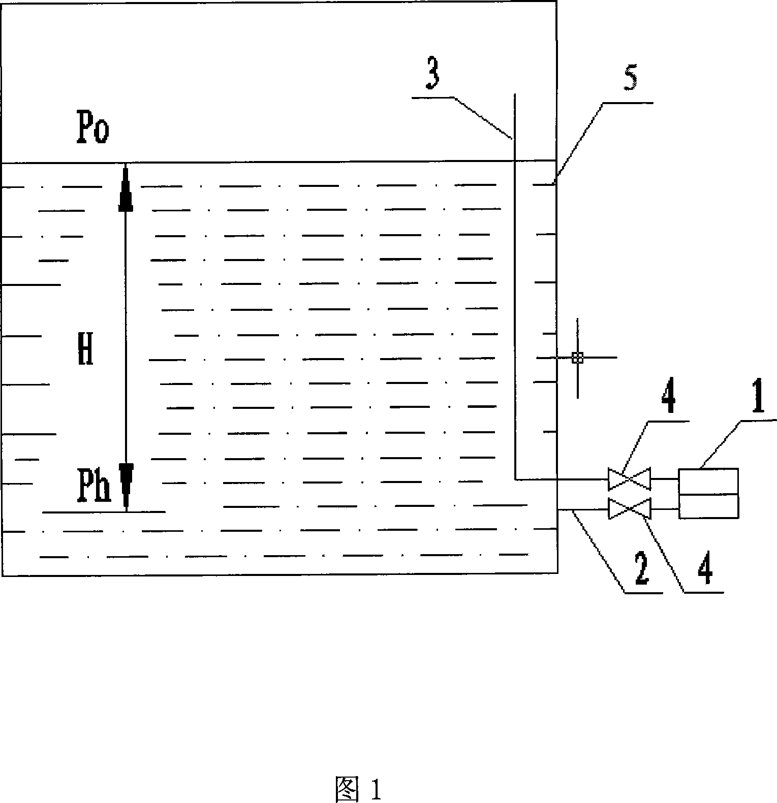
[0025] Embodiment 1 is shown in Figure 1: it comprises liquid storage tank 5 (container), differential pressure liquid level gauge 1, positive phase pressure introduction pipe 2, negative phase pressure introduction pipe 3, positive phase pressure introduction pipe 2 and negative phase The pressure introduction pipe 3 is respectively connected to the positive phase end and the negative phase end of the differential pressure liquid level gauge 1 , and the negative phase pressure introduction pipe 3 extends upwards above the highest liquid level in the liquid storage tank 5 . The negative phase pressure guide pipe 3 is pre-filled with the medium to be contained in the liquid storage tank 5, and then the differential pressure liquid level gauge 1 is negatively shifted (zeroed). When it is used to measure a medium with relatively stable physical properties, it is not necessary to inject a solution into the negative phase pressure introduction tube 3 .

Embodiment 2

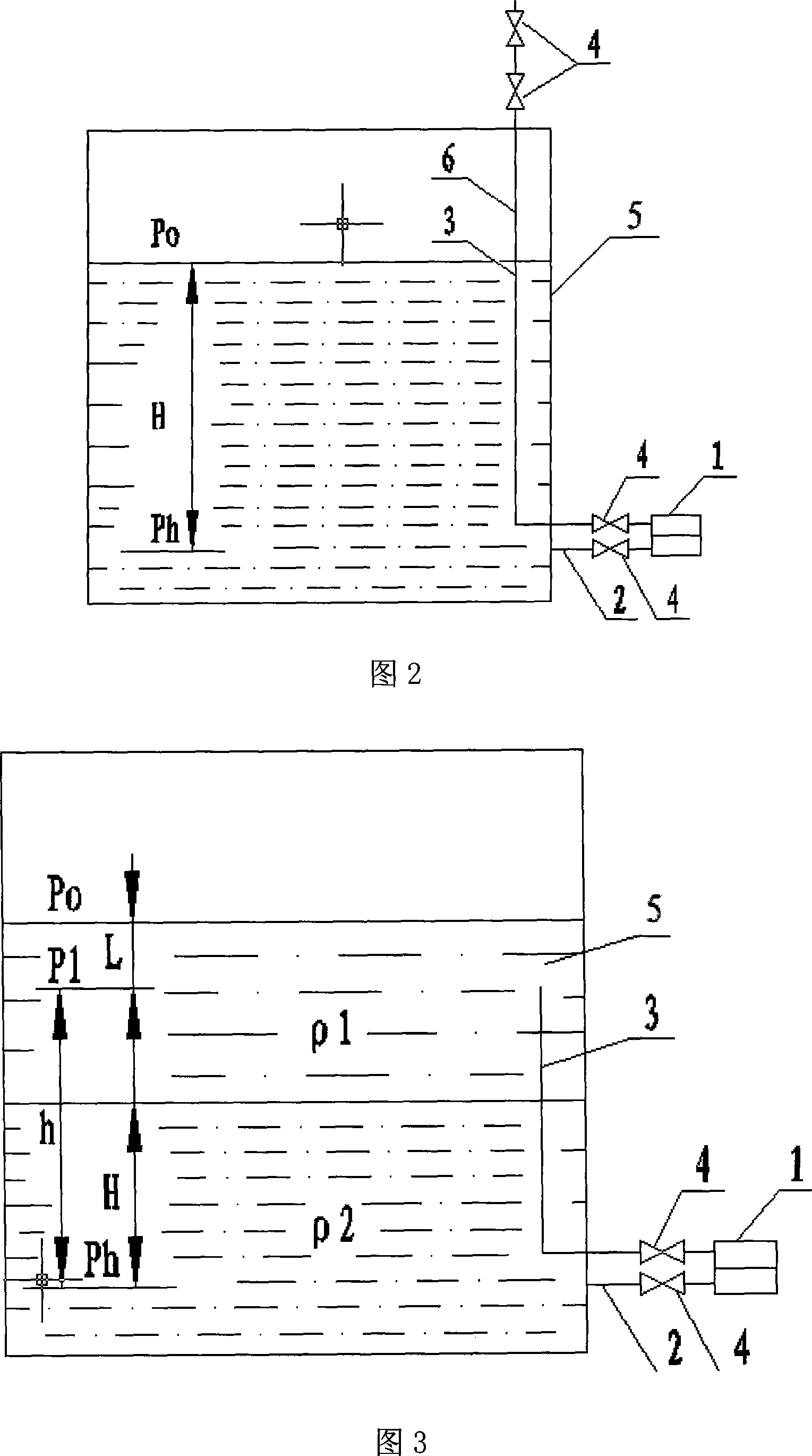
[0026] Embodiment 2 is shown in Figure 2: it is an improved method of the built-in pressure-taking method of the differential pressure liquid level gauge. The upper end of the phase pressure pipe 3 (higher than the upper limit of the liquid to be measured) has a small hole 6, and a plurality of small holes can be opened. Before the liquid level gauge is used, the medium to be loaded in the future container is pre-injected into the negative phase pressure induction pipe 3, and the liquid level in the negative phase pressure induction pipe 3 rises to the bottom of the small hole 6 (at this time, if the liquid injection continues The level will not rise), and then perform negative shift (zero adjustment) to the differential pressure level gauge 1.

[0027] If it is impossible to judge the liquid injection volume, it is also possible to perform excessive negative migration on the differential pressure liquid level gauge 1 before the liquid injection, that is, the negative migratio...

Embodiment 3

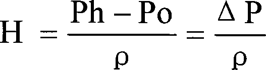
[0032] Embodiment 3 is shown in Figure 3: the differential pressure liquid level gauge 1 is used to measure the interface height between two liquids, and the height of the upper end of the negative phase pressure guiding pipe 3 should be guaranteed to be in the upper liquid (liquid with lower density) . The upper layer liquid in the container can be injected into the negative phase pressure induction pipe 3 in advance, or it can be poured into the negative phase pressure induction pipe 3 by itself after the container is filled with liquid. The liquid level gauge does not need to perform negative migration (zero adjustment), but only needs to calibrate the range (the calculated value can be used for dry calibration when the requirements are not high).

[0033] At this time, Ph=Po+Lρ1+(h-H)ρ1+Hρ2

[0034] ρ1——the density of light liquid in the upper layer ρ2——the density of heavy liquid in the lower layer

[0035] Convert the above formula to get

[0036] Ph-(Po+Lρ1)=hρ1-Hρ1+...


PUM


Abstract

The invention belongs to the liquid level instrument, in particular to a built-in pressure tapping method of a differential pressure type level gauge, which at least comprises a liquid storage tank (5), a differential pressure type level gauge (1), a positive phase pressure guiding pipe (2) and a negative phase pressure guiding pipe (3); the positive phase pressure guiding pipe (2) and the negative phase pressure guiding pipe (3) are respectively connected with a positive end and a negative end of the differential pressure type level gauge (1). The invention is characterized in that: a vertical section of the negative phase pressure guiding pipe (3) is arranged inside a vessel, liquid contained by the vessel is prearranged into the negative phase pressure guiding pipe (3), the invention can remove the influence on measuring due to vapor or medium temperature variation in the vessel, meanwhile, the structure is simple, the operation is easy and the maintenance cost is low.

Description

technical field [0001] The invention belongs to a liquid level instrument, in particular to a built-in pressure taking method for a differential pressure liquid level meter. Background technique [0002] The measurement principle of the differential pressure level gauge is: use a thin steel pipe to connect the positive pressure end of the differential pressure gauge to the bottom of the liquid to be measured, and the other negative pressure end to the gas phase. According to the principle of hydrostatics: [0003] Ph=Po+Hρ ρ——liquid density [0004] Convert the above formula to get [0005] Liquid level height H = Ph - Po ρ = ΔP ρ [0006] Differential pressure (pressure) liquid level measurement has no moving mechanical parts, reliable operation, stable quality, long life, simple structure, convenient installation, easy o...

Claims


Application Information

Patent Timeline
Patent Type & Authority Applications(China)
IPC IPC(8): G01F23/14
Inventor 聂华张帆
Owner XIAN CHANGQING TECH ENG
Why Eureka
Try Eureka