Power capacitor protector

A technology of power capacitors and protectors, applied in emergency protection circuit devices, electrical components, etc., can solve the problem of inability to realize special fault protection of power capacitors

Inactive Publication Date: 2008-06-25
蔡甫寒
View PDF0 Cites 2 Cited by
  • Summary
  • Abstract
  • Description
  • Claims
  • Application Information

AI Technical Summary

Problems solved by technology

But for a long time, the protection of power capacitors has basically adopted the protection method of thermal relays. The thermal relay itself is used for thermal overload protection of motors, and its inherent functional characteristics cannot realize special fault protection for power capacitors. With the development of electronic technology Progress, only by using the working principle of electronic circuits to design electronic power capacitor protectors can be closest to the actual protection needs of power capacitors

Method used


Image

  • Power capacitor protector
  • Power capacitor protector

Examples


Embodiment Construction

[0015] The embodiments are further described below with reference to the accompanying drawings.

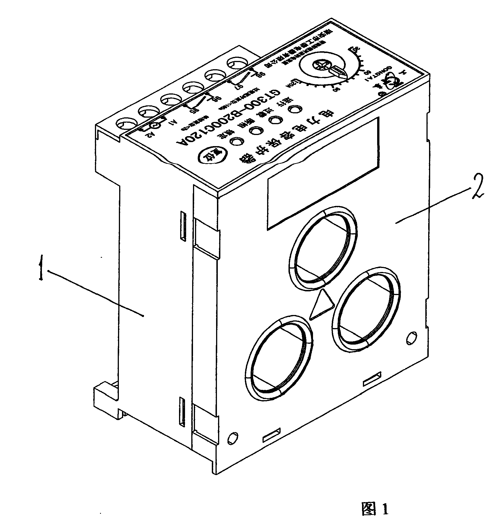
[0016] Referring to Figure 1, 1-combined housing, 2-combined housing, the two housings are snap-connected and assembled. A current transformer and an electronic component board are installed in the housing.

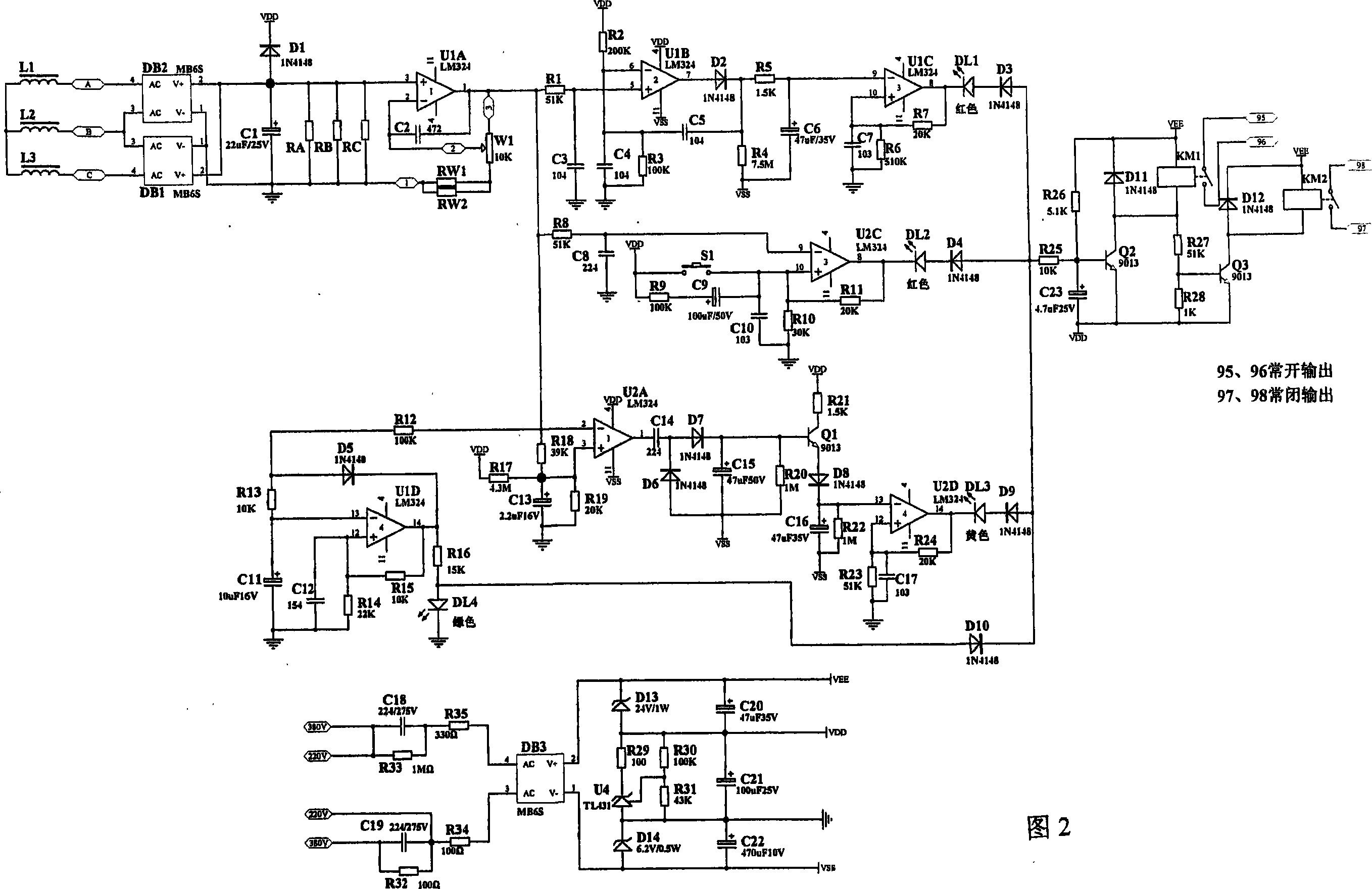
[0017] Referring to Figure 2, it is a schematic diagram of the circuit. It reflects the components of the current signal detection circuit, the power indicator circuit, the overload control circuit, the severe overload and manual reset control circuit, the phase failure protection control circuit, the drive output circuit and the power supply circuit installed on the electronic component board. As shown in the figure, the electrolytic capacitors, chip capacitors, safety capacitors C18C19, SMD diodes, voltage regulator SMD diodes, SMD rectification order flow stacks, in-line light-emitting diodes, relays KM1, KM2, SMD NPN transistors Q1, Q2, Q3, chip resistors, signal resist...


PUM


Abstract

The invention relates to protective equipment of an electric power capacitor, in particular to a protector of an electronic type electric power capacitor. The invention is characterized in that a current transformer, and an electronic component are installed in a casing body; wherein, the electronic component comprises an electrical current signal detecting circuit, a power supply indication circuit, an overcharging control circuit, a severe overcharging and manual resetting control circuit, phase protecting control circuit, a driving output circuit and a power supply circuit, and other a plurality of circuits. The electrical current signal on the electric power capacitor is detected by the current transformer in a splitting phase, divided into four circuits and outputs to the power supply indication circuit, the overcharging control circuit, the severe overcharging and manual resetting control circuit and the phase protecting control circuit after being enlarged by an operational amplifier UIA and being detected, and then connected to the driving output circuit; the power supply circuit is divided into three voltage classes and connected with the inlet wire terminals and the grounding terminals of the power supplies of the four circuits. The invention has the advantages of complete protection performance, high precision and scientific control and rationalized self-returning and self-locking properties, and the invention is widely applied to the complete set of the reactive power compensation equipment.

Description

technical field [0001] The invention relates to power capacitor protection equipment, in particular to an electronic type power capacitor protector. Background technique [0002] Power capacitors are in a long-term loading state and are often impacted by overvoltage and overcurrent caused by various abnormal factors in the power grid. When the voltage and current in the system exceed the rated limit of the capacitor, the internal dielectric loss of the capacitor will increase, resulting in overheating. Accelerates insulation aging, reduces service life, and may cause dielectric breakdown in severe cases, causing a branch failure behavior to cause the entire network to trip, resulting in repeated failures. Therefore, certain protection measures must be taken for the power capacitors of each branch in the power factor compensation. However, for a long time, the protection of power capacitors has basically adopted the protection method of thermal relays. Thermal relays themsel...

Claims


Application Information

Patent Timeline
Patent Type & Authority Applications(China)
IPC IPC(8): H02H7/16
Inventor 蔡甫寒周挺巧介国安
Owner 蔡甫寒
Why Eureka
Try Eureka