Method for measuring the actual porosity of the watertightness barrier of a fluid containment tank

A technology for sealing baffles and fluids, applied in the direction of measuring the acceleration and deceleration rate of fluids, testing of fluid tightness, methods of container discharge, etc., which can solve the problems of scarcity, reduction, and expensive stable cavity cycles.

Inactive Publication Date: 2008-07-02
STX EUROPE
View PDF0 Cites 9 Cited by
  • Summary
  • Abstract
  • Description
  • Claims
  • Application Information

AI Technical Summary

Problems solved by technology

[0042] Stabilization chamber cycles are now expensi...

Method used


Image

  • Method for measuring the actual porosity of the watertightness barrier of a fluid containment tank
  • Method for measuring the actual porosity of the watertightness barrier of a fluid containment tank
  • Method for measuring the actual porosity of the watertightness barrier of a fluid containment tank

Examples


Embodiment Construction

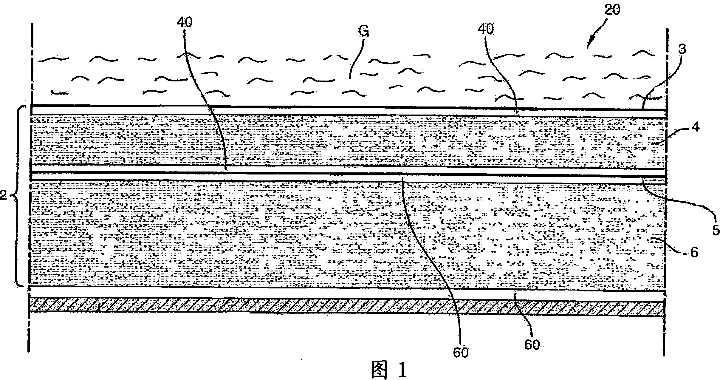
[0066] According to the invention, the air pressure in the free space 40 of the first thermal insulation layer 4 and in the free space 60 of the second thermal insulation layer 6 is adjusted according to the following criteria, whereby a stable range of measurements can be obtained, wherein the second thermal insulation layer can be carried out 6 different consistent measurements of air pressure and temperature in free space.

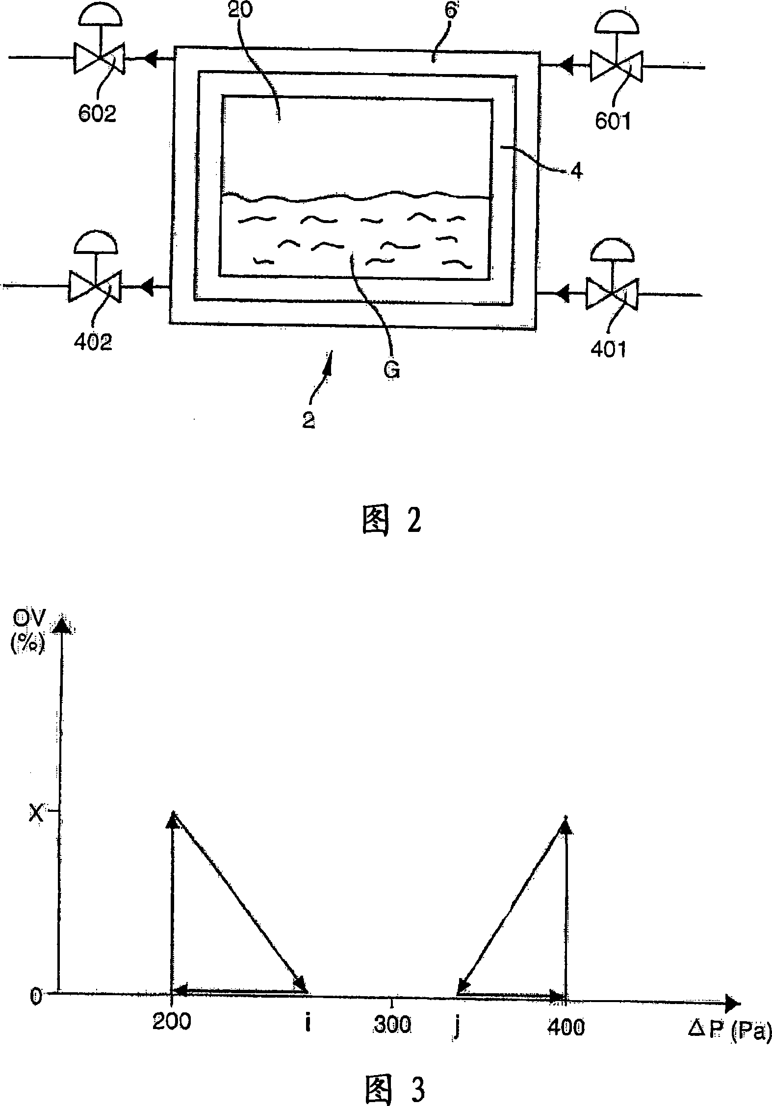
[0067] More specifically, the opening and closing of the supply valve 401, 601 and the discharge valve 402, 602 for the inert gas are controlled so as to maintain the air pressure in the free space 40 of the first heat insulating layer 4 at a value within the reference range, and The air pressure in the free space 60 of the second insulating layer 6 is kept at a difference ΔP from the air pressure in the free space of the first insulating layer 4 .

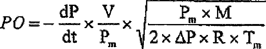
[0068] Preferably, the opening and closing of said valves 401, 601, 402 and 602 are controlled so as to ...


PUM


Abstract

The method involves measuring values of pressure and absolute temperature inside a free space (60) of a thermal insulation layer (6) at two instants during closing of inert gas i.e. nitrogen, intake and discharge valves (601, 602) or stable usage conditions of an insulated storage tank (20) e.g. membrane tank, to calculate layer's average pressure and temperature. Actual porosity of liquid/gas proof barrier is calculated based on specific formula comprising parameters such as rate of change of pressure inside the space, volume of the space, molar mass of inert gas and perfect gas constant.

Description

technical field [0001] The present invention relates to the technical field of tanks for the storage of thermally insulated fluids, such as liquefied gases, known as membrane tanks. Such tanks are mounted in the housing of the cargo chamber, such as a methane storage tank. [0002] More particularly, the invention relates to a method for measuring the actual porosity of one of the sealing layers of such tanks. Background technique [0003] The structure of the wall of such a tank will be briefly described below with reference to FIG. 1 . Figure 1 is a schematic cross-sectional view of the wall of a tank containing liquefied gas. [0004] A liquefied gas G, such as methane, is stored in a tank 20, the walls of which are secured to the casing 1 of the chamber by any suitable securing means. [0005] The housing of the cavity may be a single housing or more generally a double housing construction. In Fig. 1, reference numeral 1 denotes the inner wall of the housing. This s...

Claims


Application Information

Patent Timeline
IPC IPC(8): G01N7/10G01N15/08G06F17/13
CPCF17C2223/0161F17C13/001F17C2221/033F17C2270/0107F17C2270/0105G01N15/088G01M3/32F17C2203/0631G01M3/00G01M3/26
Inventor C·迪弗洛P·埃斯伯兰
Owner STX EUROPE
Why Eureka
Try Eureka