Test device for asphalt mixture resisting moving water scouring

A technology of asphalt mixture and test device, which is applied in the direction of measuring device, material inspection product, analysis material, etc., can solve the problem of not being able to evaluate the scouring effect of asphalt mixture well.

Inactive Publication Date: 2008-07-02
HARBIN INST OF TECH
View PDF0 Cites 36 Cited by
  • Summary
  • Abstract
  • Description
  • Claims
  • Application Information

AI Technical Summary

Problems solved by technology

[0003] The purpose of the present invention is to solve the problem that there is no test device that can well evaluate the scouring effect of dynamic water on asphalt mixture, and to provide a test device for asphalt mixture that can simulate the joint action of load, water and temperature

Method used


Image

  • Test device for asphalt mixture resisting moving water scouring
  • Test device for asphalt mixture resisting moving water scouring
  • Test device for asphalt mixture resisting moving water scouring

Examples


specific Embodiment approach 1

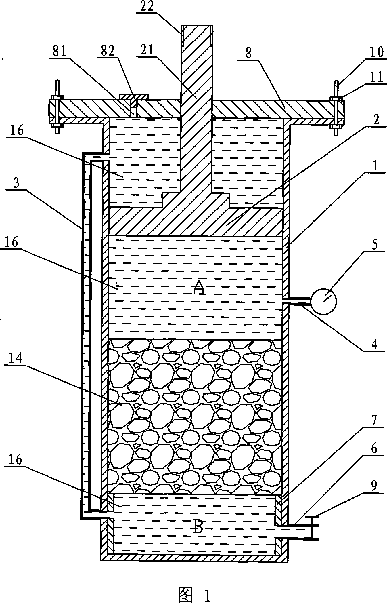
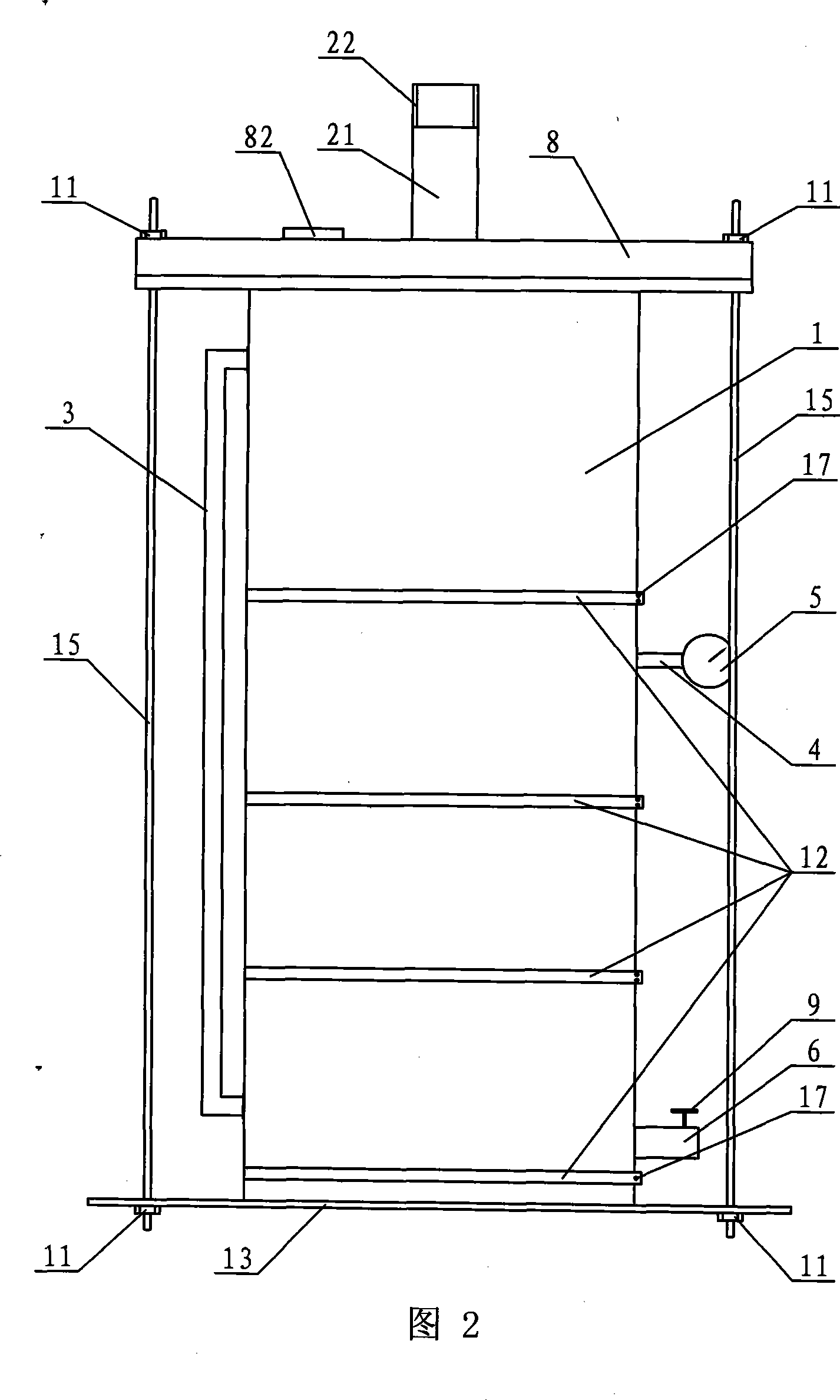
[0007] Specific Embodiment 1: This embodiment is described in conjunction with FIG. 1. This embodiment consists of a flushing barrel 1, a piston 2, a conduit 3, an upper water pipe 4, a pressure gauge 5, a lower water pipe 6, a support 7, an upper cover 8 and a valve. 9 components, the bottom of the inner cavity of the flushing barrel 1 is provided with a support 7, the upper part of the inner cavity of the flushing barrel 1 is provided with a piston 2, the top of the flushing barrel 1 is provided with an upper cover 8, and the upper end of the conduit 3 is arranged on the side of the flushing barrel 1. Above the wall, the lower end of the conduit 3 is arranged below the side wall of the flushing barrel 1, the upper water pipe 4 is arranged on the side wall of the flushing barrel 1, the upper water pipe 4 is provided with a pressure gauge 5, and the side wall of the flushing barrel 1 is provided below There is a lower water pipe 6 with a valve 9 on the lower water pipe 6. The l...

specific Embodiment approach 2

[0008] Specific Embodiment 2: This embodiment is described with reference to FIG. 1 . In this embodiment, the tail of the piston rod 21 on the piston 2 is provided with an external thread 22 . The external thread 22 is used to connect the piston rod 21 with the upper pressure head of the testing machine.

specific Embodiment approach 3

[0009] Specific embodiment three: this embodiment is described in conjunction with Fig. 1, the difference between this embodiment and specific embodiment one is: this embodiment also adds a rubber stopper 82, the upper cover 8 is provided with an air hole 81, and the rubber stopper 82 is arranged on In the air hole 81. Such design is to discharge the gas in the flush bucket 1 . Other components and connections are the same as those in the first embodiment.


PUM

PropertyMeasurementUnit
thicknessaaaaaaaaaa
thicknessaaaaaaaaaa

Abstract

The invention relates to a test device, specifically to a flowing water washout prevention test device for asphalt mixture. The invention aims to solve the problem that no test device is available for evaluating the washout effect of flowing water on asphalt mixture. In the inventive device, a pedestal is disposed at the bottom of the inner cavity of a washout barrel (1), a piston (2) is disposed on the inner cavity of the washout barrel (1), an upper cover is disposed at the top end of the washout barrel (1), a conduit (3) and an upper water pipe (4) are disposed at the side wall of the washout barrel (1), a pressure meter (5) is disposed on the upper water pipe (4), and a lower water pipe (6) is disposed in the lower part of the side wall of the washout barrel (1) and provided with a valve (9). The invention can simulate the effect of flowing water pressure arising from vehicle traveling on the asphalt concrete pavement on the asphalt pavement under different temperature conditions.

Description

technical field [0001] The invention relates to an anti-dynamic water erosion test device. Background technique [0002] Natural precipitation is removed by the cross slope of the road surface. The road surface in rainy days is often covered by a layer of water film. The tires 18 running at high speed act, thus generating hydrodynamic pressure. When the wheels drive to the road gap 20, a positive pressure is generated on the road water, and the water is squeezed into the road gap 20, as shown in Figure 3; Water is sucked out from the pavement gap 20, as shown in Figure 4; conventional asphalt mixture technical requirements are sufficient to resist the action of hydrodynamic pressure, but for high-grade highways, the driving speed is above 110km / h, the resulting hydrodynamic The pressure can reach 2.5-3.0 times that of ordinary roads. The strong hydrodynamic pressure will force rainwater to enter the road surface and directly act on the interface between asphalt and aggrega...

Claims


Application Information

Patent Timeline
Patent Type & Authority Applications(China)
IPC IPC(8): G01N17/00G01N3/56G01N33/38
Inventor 谭忆秋胡斌侯明昊
Owner HARBIN INST OF TECH
Why Eureka
Try Eureka