Photo-acoustic spectrometer apparatus

A spectrometer, equipment technology, applied in the field of spectrometer equipment and spectroscopy, can solve problems such as lack of sensitivity

Inactive Publication Date: 2008-07-02
KONINKLIJKE PHILIPS ELECTRONICS NV
View PDF0 Cites 16 Cited by
  • Summary
  • Abstract
  • Description
  • Claims
  • Application Information

AI Technical Summary

Problems solved by technology

Unfortunately, the technique lacks sensitivity

Method used


Image

  • Photo-acoustic spectrometer apparatus
  • Photo-acoustic spectrometer apparatus

Examples


Embodiment Construction

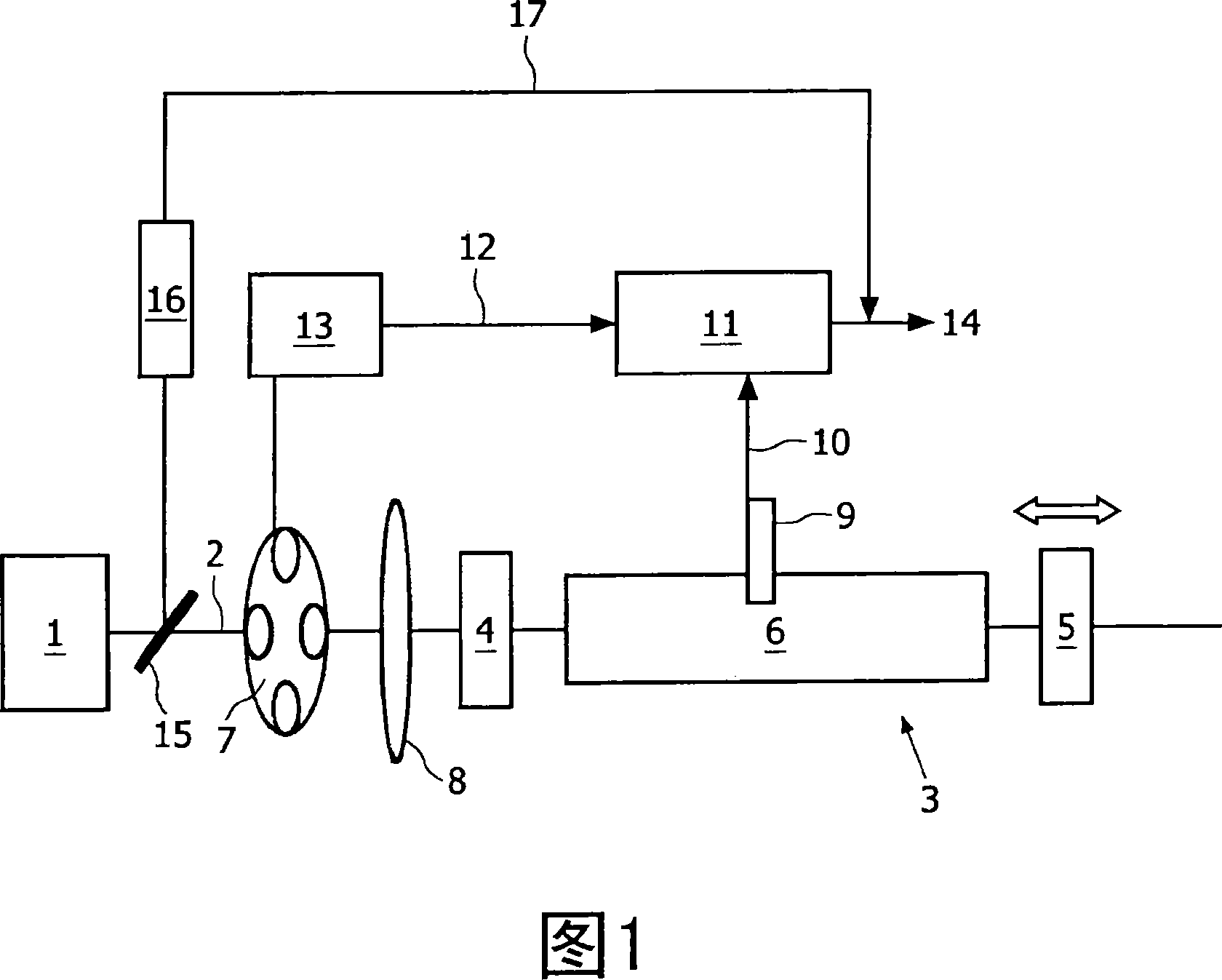
[0024] A continuous wave laser source 1 emits a laser beam 2 with a preselected wavelength towards a high-Q laser cavity 3 bounded by a first cavity mirror 4 and a second cavity mirror 5 . The laser light enters the optical cavity 3 when the wavelength of the laser light coincides with the wavelength of one of the cavity modes of the cavity 3 , thereby coupling the beam 2 into the cavity 3 .

[0025] Dithering the wavelength of the laser beam 2 and / or dithering the wavelength of the cavity mode increases the probability of coupling. A piezoelectric driver (not shown) may be used to spatially modulate an etalon (not shown) placed within the laser, thereby dithering the laser wavelength.

[0026] Wavelength dithering of the cavity mode can be achieved by spatially modulating one of the cavity mirrors, for example by driving the second mirror 5 back and forth with a piezoelectric driver (not shown).

[0027] In order to further increase the coupling probability, the geometry of ...


PUM


Abstract

The photoacoustic detection chamber (6) is located in the optical cavity (3) of the cavity-enhanced absorption spectroscopy device (3, 4, 5). When the sample in the chamber (6) absorbs radiation from the pulsed radiation beam coupled into the cavity (3), pressure waves detected by the microphone (9) are generated. The detection signal (10) output by the microphone (9) can be processed to determine the concentration value of the absorbing material in the sample.

Description

technical field [0001] The present invention relates to a spectrometer device and a spectroscopic method, in particular to but not limited to a laser spectrometer device and a laser spectroscopic method. Background technique [0002] It is known to analyze the composition of samples using laser absorption spectroscopy techniques. For example, it could be used to detect pollutants in air samples, or to detect biomarkers in breath samples. There are several different laser absorption spectroscopy techniques known. [0003] Among these known techniques, direct absorption spectroscopy is the most basic. In this technique, a sample contained in an absorption cell is analyzed using a light source, an absorption cell, and a photodetector. As light from the light source passes through the absorbing chamber, the gas in the chamber absorbs some of the light. A photodetector is located behind the absorption chamber and is used to measure how much light is absorbed. The concentrati...

Claims


Application Information

Patent Timeline
Patent Type & Authority Applications(China)
IPC IPC(8): G01N21/39G01N29/24G01J3/433H01S3/139
CPCG01J3/10G01J3/4338G01N21/1702G01N21/39G01N29/032G01N29/2425G01N2021/391G01N2201/0696G01N2291/0215
Inventor M·范赫佩恩
Owner KONINKLIJKE PHILIPS ELECTRONICS NV
Why Eureka
Try Eureka