

Bladder renal pelvis stones extraction lens
A technology of renal pelvis and stone mirror, which is applied in the field of bladder and kidney stone mirror, which can solve the problems of single function, limited use, and inability to fix stones, etc.
- Summary
- Abstract
- Description
- Claims
- Application Information
AI Technical Summary
Problems solved by technology
Method used
Image

Examples
Embodiment Construction
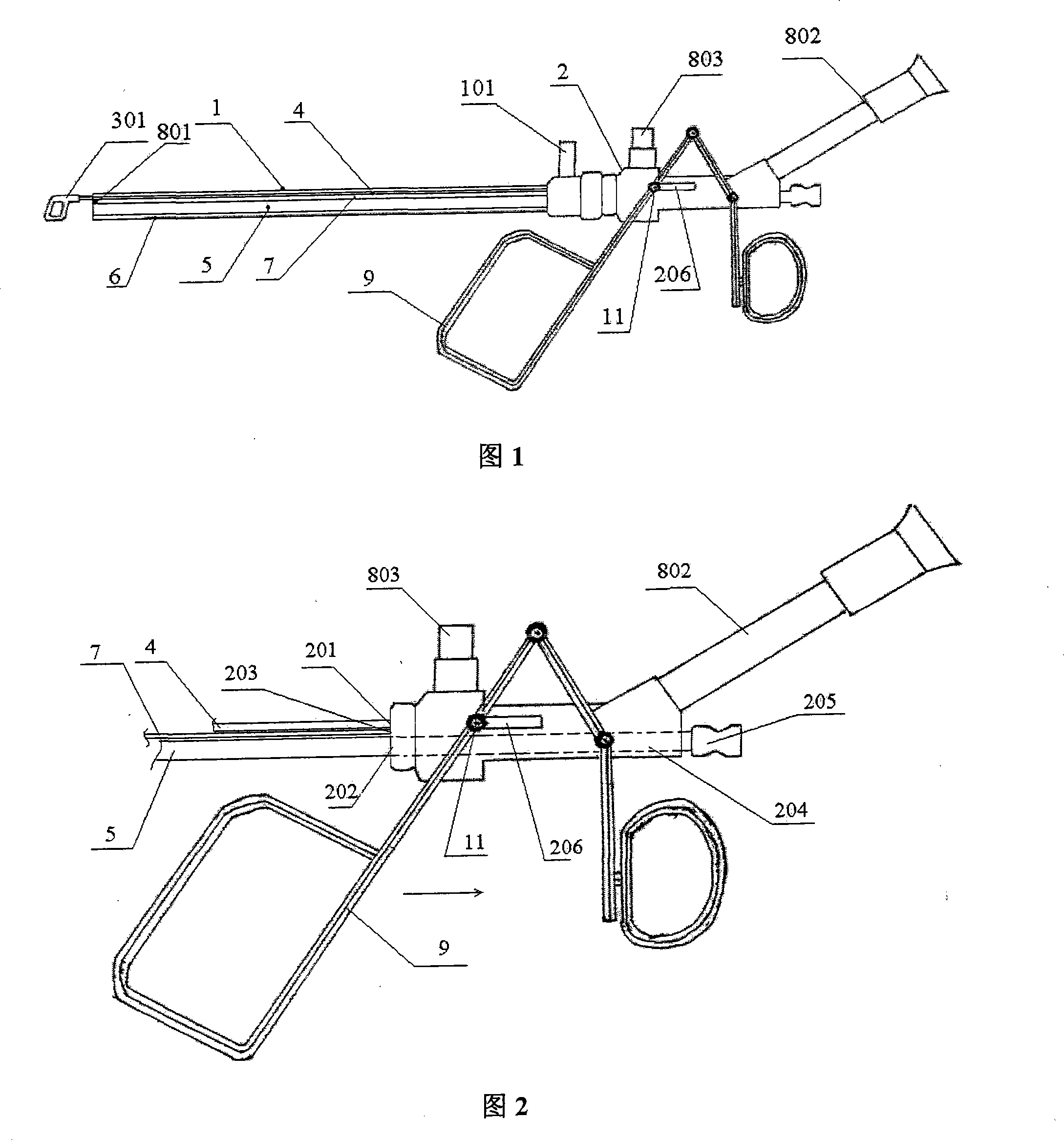
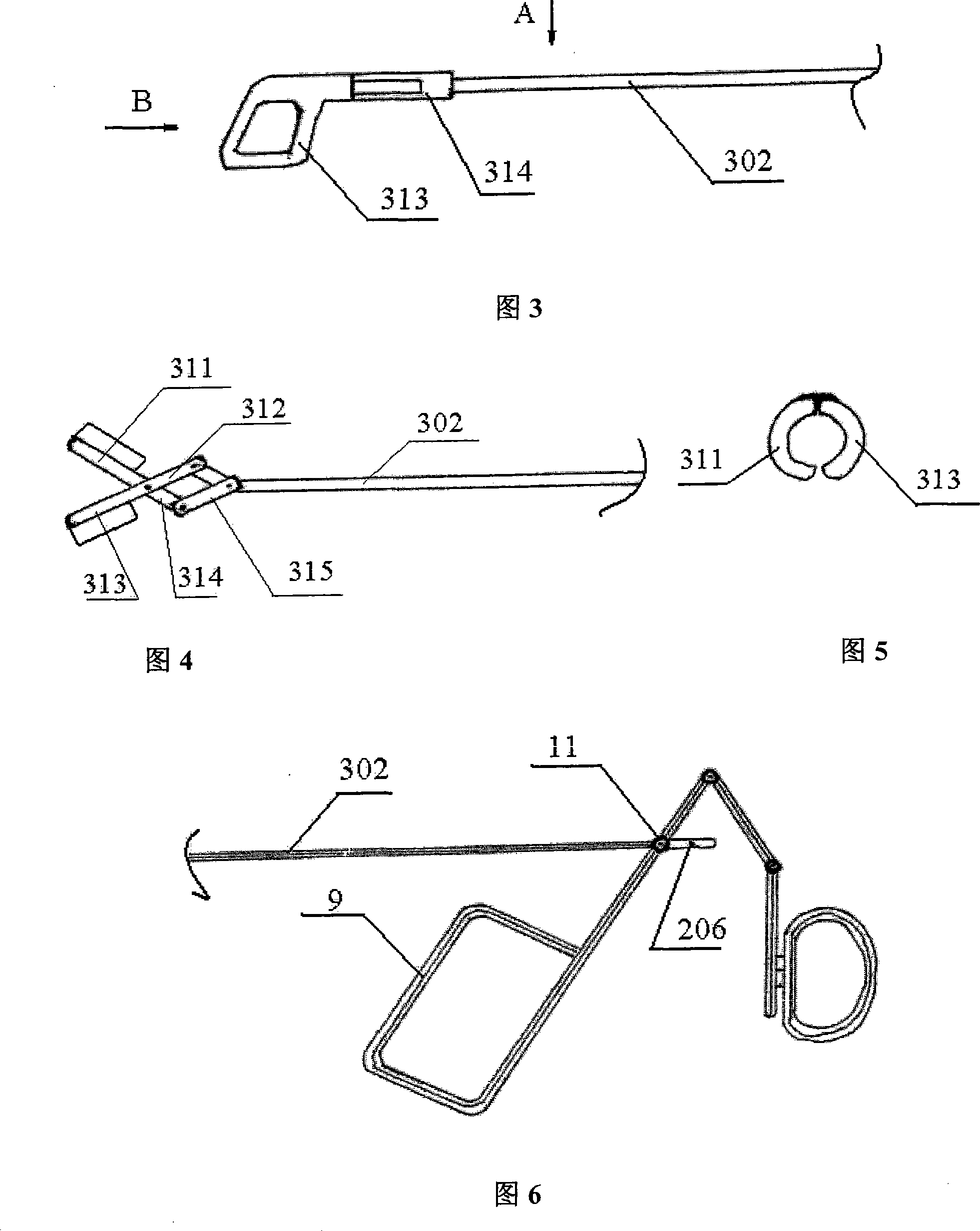
[0022] Referring to Fig. 1 and Fig. 2, the vesico-kidney stone extraction mirror of the present invention comprises a straight tubular mirror sheath 1 and a mirror body 2 with both ends open, and said mirror body 2 is connected to one end of the mirror sheath 1;
[0023] It is characterized in that it also includes a stone extraction forceps assembly, a stone extraction forceps channel tube 4, a gravel channel tube 5, an optical fiber channel tube 7, and an endoscopic imaging component;
[0024] The end of the mirror sheath 1 is provided with a flushing liquid channel port 101 communicating with the inner cavity;
[0025] One end of said stone extraction forceps channel tube 4, gravel channel tube 5 and optical fiber channel tube 7 communicates with the pull rod inlet 201 on the mirror body 2, the gravel channel port 202 and the optical fiber inlet 203 respectively, and the other end is inserted into the mirror body. In the sheath 1 and extending to the end of the mirror sheat...
PUM
 Abstract
Description
Claims
Application Information