
Mold special for coupler yoke frame and demoulding method

A hook tail frame and mold technology, which is applied in the direction of manufacturing tools, forging/pressing/hammer devices, forging/pressing/hammering machinery, etc., can solve the problems of difficult positioning of shearing, high labor intensity, long time for hook tail frames, etc. , to achieve the effects of easy automation, labor saving and low labor intensity

Inactive Publication Date: 2010-06-23
曾德文
View PDF0 Cites 0 Cited by
  • Summary
  • Abstract
  • Description
  • Claims
  • Application Information

AI Technical Summary

Problems solved by technology

[0002] Most of the existing hook tail frames are formed by molding, and the special mold is composed of upper and lower molds. When the upper mold and the lower mold are fastened together, the cavity of the hook tail frame is formed between the upper mold and the lower mold. , the hook tail frame needs to be demolded. However, after the existing special mold is formed, the demoulding can only be manually pried from one or both ends. This demoulding method has the following problems:
[0003] 1) When prying, it is a point contact, and the action point is on the flash formed when the coupler frame is formed. Due to the local force and the low strength of the flash, the flash is easy to deform, so it is not easy to shear in the subsequent process. positioning, resulting in waste generation or increase
[0004] 2) The efficiency of manual prying is low and it is not easy to pry out, so the coupler frame stays in the mold cavity for a long time, which is easy to cause deformation of the inner surface of the mold and shorten the life of the mold
[0005] 3), the labor intensity of workers prying is high, the work efficiency is low, and it cannot be automated

Method used


Image

  • Mold special for coupler yoke frame and demoulding method
  • Mold special for coupler yoke frame and demoulding method
  • Mold special for coupler yoke frame and demoulding method

Examples


Embodiment 1

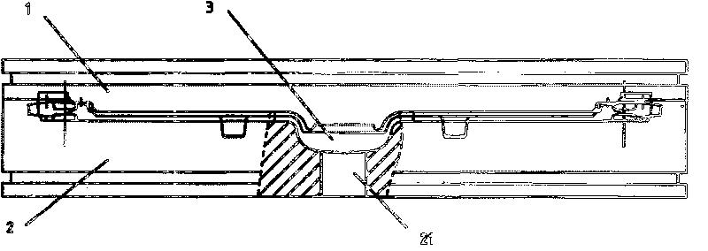
[0028] like figure 1 As shown, the special mold of the present invention comprises an upper mold 1 and a lower mold 2, a cavity 3 of the hooktail frame is formed between the upper mold 1 and the lower mold 2, and at least one through hole 21 is provided at the bottom of the lower mold 2. In this embodiment In an example, there is one through hole, and the upper end of the through hole 21 is connected to the cavity 3 . After the forging and pressing of the hook tail frame, it is only necessary to set a push rod in the through hole 21, and then act on the push rod to move upwards, and the hook tail frame connected to the upper end of the through hole 21 can be jacked up to realize quick demoulding .

Embodiment 2

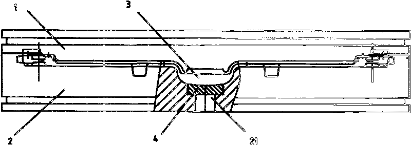
[0030] like figure 2 As shown, at least one through hole 21 is provided on the lower mold 2, and in this embodiment, there is one through hole, and a groove is also arranged at the position of the through hole 21 of the lower mold 1, and a groove is set in the groove There is a movable block 4, through hole 21 links to each other with the movable block 4, the shape of the movable block 4 can be circular, rectangular or any shape, the size of the upper surface area is determined according to the number of through holes, when there are many through holes, the movable block 4 The area of ​​the movable block 4 can be relatively small, and a rod can be fixedly connected to the lower end of the movable block 4, and the rod passes through the through hole 21. After the hooktail frame is forged and formed by the die, the ejector rod in the through hole 21 first acts on the movable block 4, and then acts on the hooktail frame through the movable block 4, changing the small acting surf...

Embodiment 3

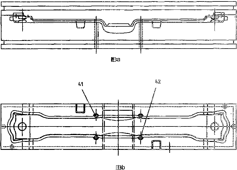
[0032] like image 3 As shown, at least one through hole is provided on the shell walls on both sides of the lower mold 2, and the position of the through hole is just at the position of the burr generated when the coupler frame is forged and pressed. In this embodiment, each side shell wall Each of the through holes on the top is two holes 41 and 42 respectively. After the coupler frame is forged and formed by the die, the ejector rod in the hole directly acts on the flash, and the deformation of the coupler frame will not occur while demolding.


PUM


Abstract

The invention discloses a special die and demoulding method for a coupler yoke. The die includes an upper mould and a lower mould. A hollow cavity used for forging and pressing the coupler yoke is formed between the upper mould and the lower mould. The die also includes a demoulding mechanism which includes at least one through hole arranged on the lower mould. The technical scheme adopted by thedemoulding method relates to: arranging a top rod in the through hole of the lower mould of the die and simultaneously applying an upward force on the top rod to jack up the formed coupler yoke so asto realize demoulding. Compared with the prior art, the special die of the coupler yoke of the invention has the advantages of simple structure, reliable action, labor saving and being easy to realize automatization, etc. The demoulding method of the invention has the advantages of low working intensity, fast demoulding, simple and effective method; simultaneously being easy to realize automatization, improve the producing efficiency and reduce the manufacture cost.

Description

technical field [0001] The invention relates to a special mold and a demoulding method, in particular to a special mold and a demoulding method for a coupler frame. Background technique [0002] Most of the existing hook tail frames are formed by molding, and the special mold is composed of upper and lower molds. When the upper mold and the lower mold are fastened together, the cavity of the hook tail frame is formed between the upper mold and the lower mold. , the hook tail frame needs to be demolded. However, after the existing special mold is formed, the demoulding can only be manually pried from one or both ends. This demoulding method has the following problems: [0003] 1) When prying, it is a point contact, and the action point is on the flash formed when the coupler frame is formed. Due to the local force and the low strength of the flash, the flash is easy to deform, so it is not easy to shear in the subsequent process. Positioning, resulting in waste generation or...

Claims


Application Information

Patent Timeline
Patent Type & Authority Patents(China)
IPC IPC(8): B21J13/02B21J13/14
Inventor 曾德文
Owner 曾德文
Learn More