A surface mounted magnetic element

A magnetic component, surface-mounted technology, applied in electrical components, inductors with magnetic cores, inductors, etc., can solve problems such as complex manufacturability, and achieve good processing technology, reliable fixing method, and good clamping effect. Effect

Inactive Publication Date: 2008-07-09
SUMIDA ELECTRIC H K COMPANY
View PDF1 Cites 2 Cited by
  • Summary
  • Abstract
  • Description
  • Claims
  • Application Information

AI Technical Summary

Problems solved by technology

[0004] Judging from the structure disclosed in the above patent and the description of its manufacturing process, it is necessary to bend the protrusion 4b to clamp the end of the winding, and an additional process of bending the protrusion 4b is required, and the process is relatively complicated.

Method used


Image

  • A surface mounted magnetic element
  • A surface mounted magnetic element
  • A surface mounted magnetic element

Examples


Embodiment 1

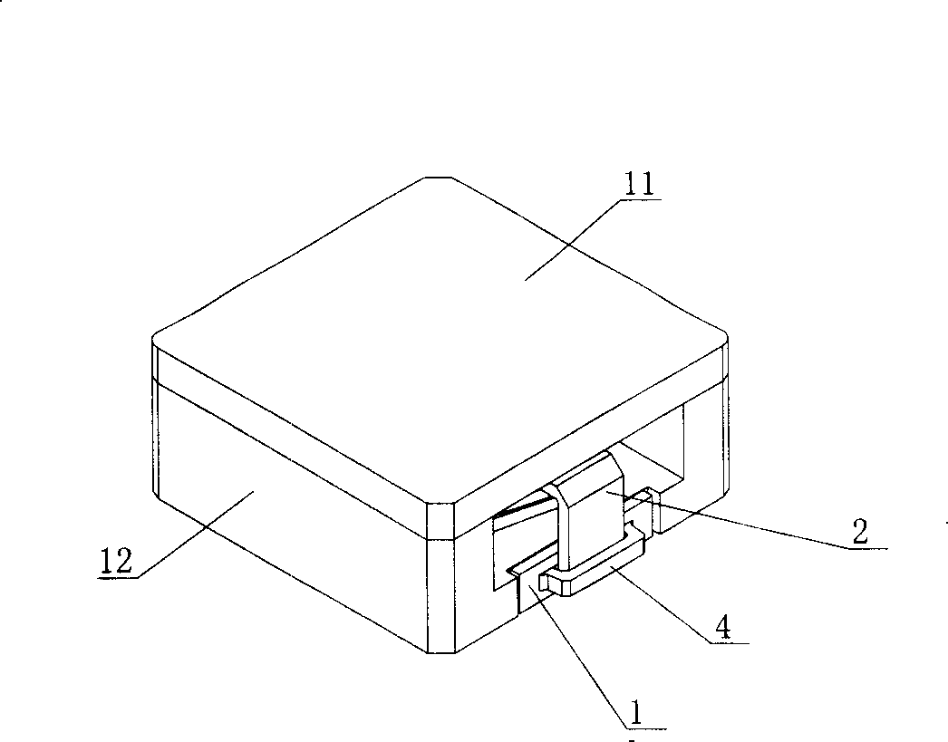
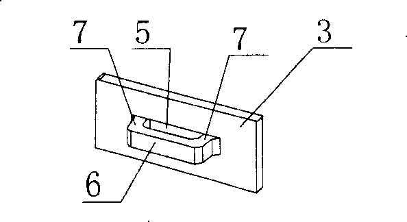
[0041] A surface-mounted magnetic component, including a coil, a magnetic core, and a metal terminal 1, wherein the metal terminal 1 is provided with a fixing part 9 for fixing with the magnetic core and a joint part for installing the coil end 2 , the joint is composed of a main body 3 of the joint, a clamp arm 4 connected to the main body 3 of the joint, and formed between the clamp arm 4 and the main body 3 of the joint for accommodating the coil end 2 The clamping space 5 constitutes.

[0042] Among them, the magnetic core is composed of a flat magnetic core 11 and an EPC magnetic core 12, the coil 11 is placed in the EPC magnetic core 12, the flat magnetic core 11 is covered on the EPC magnetic core 12, and two gaps 10 are arranged on the EPC magnetic core 12. , the two metal terminals 1 are respectively arranged on the two notches 10, and the two coil ends 2 are exposed. The joint body 3 and the arm 4 are punched and formed as a whole sheet material; the arm 4 includes ...

Embodiment 2

[0045] See Figure 10 , Figure 11 The difference between this embodiment and the first embodiment is that there are multiple clamping arms 4 on the metal terminal 1, which are arranged in parallel along the direction of the coil end 2, and the spacing between multiple clamping arms 4 is equal. Compared with the first embodiment, the fixing effect of this embodiment is better.

Embodiment 3

[0047] See Figure 12 , The difference between the present embodiment and the second embodiment is that the card arm 4 is arc-shaped. This embodiment can be used for clamping and fixing the circular or semicircular coil end 2 .


PUM


Abstract

The invention discloses a surface mounting magnetic element, including a coil, a magnetic core and a metal terminal, wherein, a fixed part which is fixed with the magnetic core and a joint part which is used for installing the tail end of the coil are arranged on the metal terminal, and the joint part is composed of a joint part main body, a clamping arm which is connected on the joint part main body and a clamping space which is formed between the clamping arm and the joint part main body and is used for containing the tail end of the coil. The magnetic element of the invention can ensure the reliably preliminary fixed connection of the tail end of the coil and the metal terminal, and the manufacturing process is simple.

Description

technical field [0001] The invention relates to a magnetic element, in particular to a surface-mounted magnetic element with improved metal terminals. Background technique [0002] In magnetic components such as EPC cores, the ends of the coil need to be electrically connected to metal terminals. When the two metal terminals are energized, a loop can be formed at both ends of the coil. In the prior art, since the surface of the metal terminal is smooth, and there will be a certain tension and deformation at the end of the coil, it is impossible to cling to the junction of the metal terminal, making the temporary fixation between the metal terminal and the end of the coil unreliable, affecting its electric current. The reliability of the connection; therefore, it is usually necessary to fix the end of the coil by hand or other utensils during operation to ensure full contact between the end of the coil and the metal terminal and to ensure the accuracy of the joint position, b...

Claims


Application Information

Patent Timeline
Patent Type & Authority Applications(China)
IPC IPC(8): H01F27/29H01F17/04H01F37/00
Inventor 黄东荣朱传梓
Owner SUMIDA ELECTRIC H K COMPANY
Why Eureka
Try Eureka