An upper laid aerial device of automobile
An antenna device and top-mounted technology, applied to antennas, devices that enable antennas to work in different bands at the same time, antenna components, etc., can solve problems such as affecting antenna reception, inconvenient use, and easy loss of antenna rods, etc., to achieve structural Compact, easy to use, beautiful appearance design effect
- Summary
- Abstract
- Description
- Claims
- Application Information
AI Technical Summary
Problems solved by technology
Method used
Image

Examples
Embodiment Construction
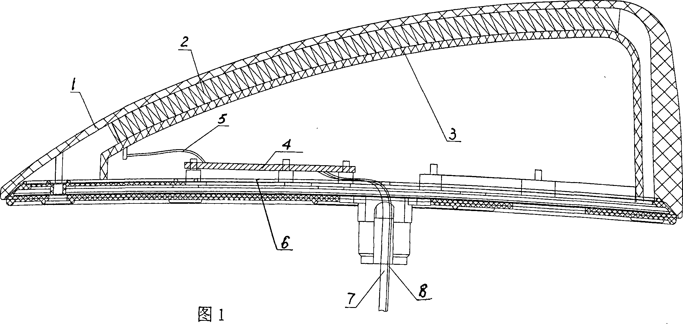
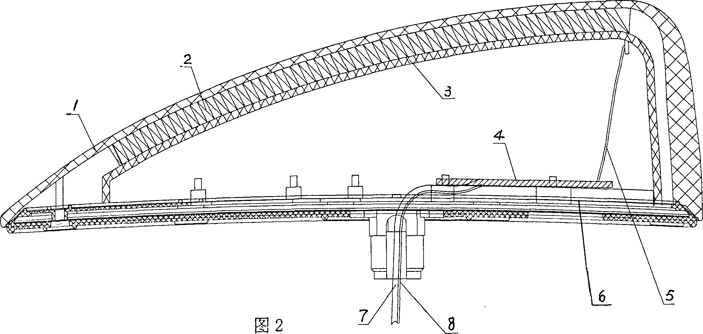
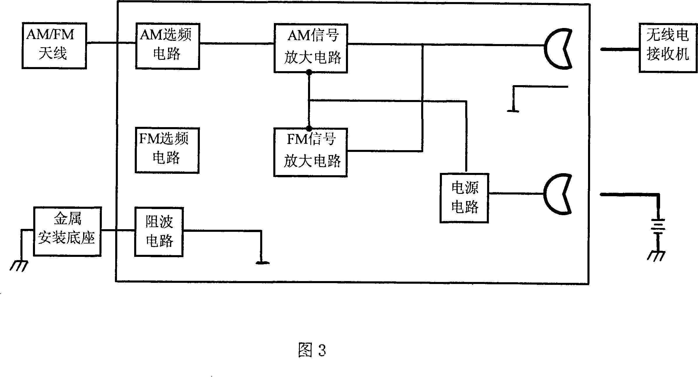
[0024] With reference to accompanying drawing 1~4, the car top antenna device structure comprises antenna housing 1, antenna bracket 3, radio receiving antenna 2, antenna amplifier 4, metal mounting base 6, wireless signal output coaxial cable 7. The radio receiving antenna 2 is installed on the antenna support 3, and the antenna support 3 is contained on the metal installation base plate 6. The radio receiving antenna 2 is an AM / FM shared antenna, and the radio receiving antenna 2 adopts a metal helical antenna, and its resonance frequency is 98±3MHz. One end of the radio receiving antenna 2 is provided with an antenna signal output end, and the antenna signal output end of the radio receiving antenna 2 is connected with the signal input end of the antenna amplifier through the connecting wire 5, and the circuit board of the antenna amplifier 4 is installed on the metal installation base plate seat 6, and the antenna amplifier signal The output end is connected with the radio...
PUM
 Abstract
Description
Claims
Application Information
PatSnap Eureka turns technology decisions into work you can execute. Powered by our Innovation Knowledge Graph, it runs expert workflows across engineering, life sciences, materials and intellectual property. Get your review-ready output in minutes.


