A PFC circuit with current sharing control module and the corresponding current sharing control method

A current control and circuit technology, which is applied in the field of two-way parallel boost PFC circuit and its current sharing control, can solve the problems of PFC circuit hardware circuit complexity, poor inductor current sharing characteristics, and inability to achieve current sharing, etc., to achieve Realize the effect of true current sharing, good current sharing characteristics, and good current sharing characteristics

Active Publication Date: 2008-07-09
EMERSON NETWORK POWER CO LTD
View PDF2 Cites 95 Cited by
  • Summary
  • Abstract
  • Description
  • Claims
  • Application Information

AI Technical Summary

Problems solved by technology

[0004] The present invention aims at the disadvantages that the above existing current sharing control circuit and method make the hardware circuit of the PFC circuit complex and the current sharing characterist

Method used


Image

  • A PFC circuit with current sharing control module and the corresponding current sharing control method
  • A PFC circuit with current sharing control module and the corresponding current sharing control method
  • A PFC circuit with current sharing control module and the corresponding current sharing control method

Examples


Embodiment 1

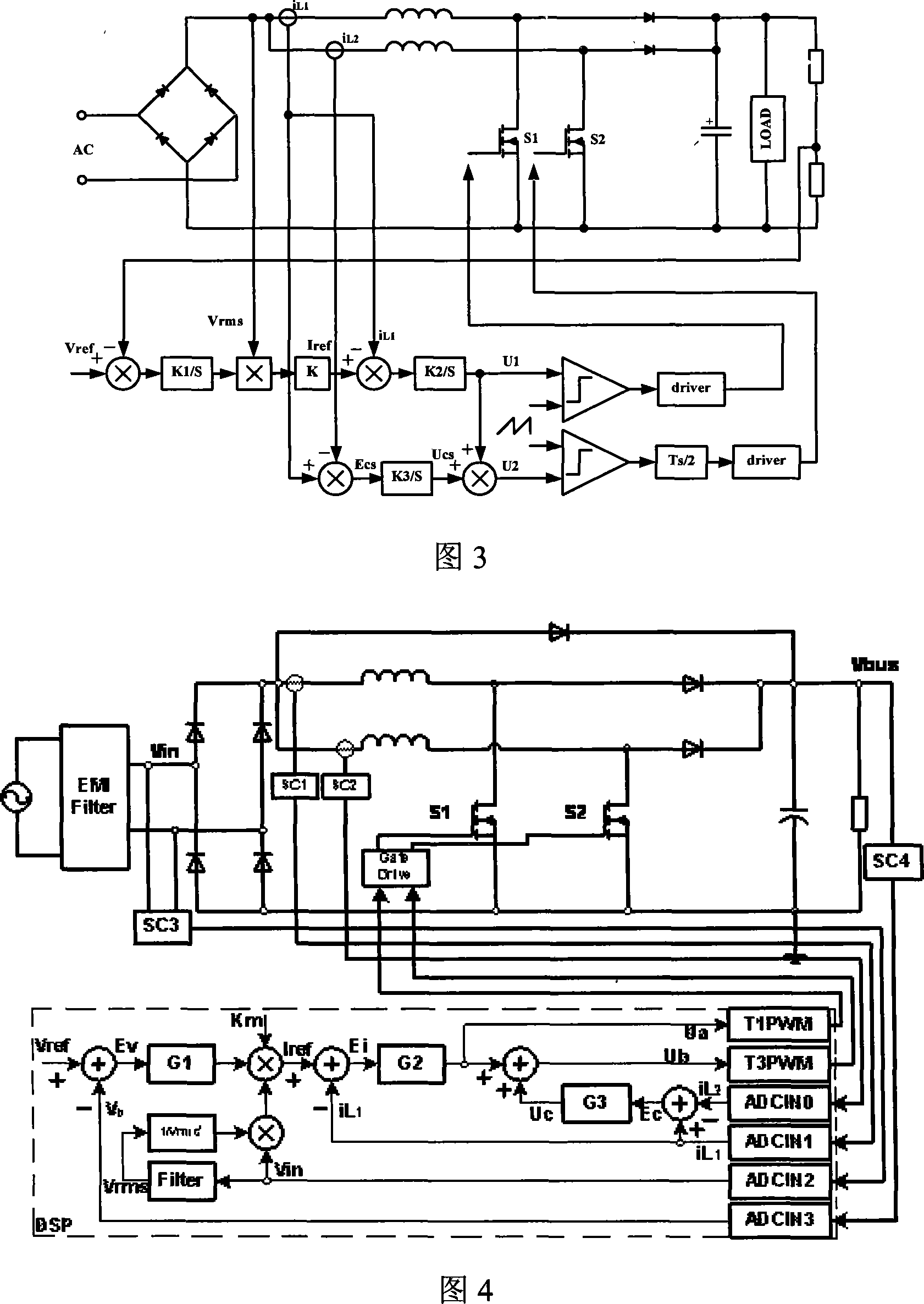
[0031]Figure 3 is a schematic diagram of an interleaved parallel boost PFC circuit with a current sharing control module according to an embodiment of the present invention, and Figure 4 is a circuit diagram of an embodiment using DSP to realize current sharing control, which is a better one in the present invention Current sharing control circuit. The parallel boost power factor correction circuit includes a first boost circuit and a second boost circuit, and its sampling circuit includes two sampling circuits SC1 and SC2 for inductive current iL1 and iL2, which are realized by a sensor circuit; the sampling of the input voltage Vin The circuit SC3 adopts a full-wave rectification circuit (or an operational amplifier circuit, etc.); the sampling circuit SC4 of the output voltage Vbus adopts a voltage dividing resistor circuit. Four input signals (inductor current iL1, iL2, input voltage Vin, output voltage Vbus feedback voltage Vb obtained through proportional calculation) ar...

Embodiment 2

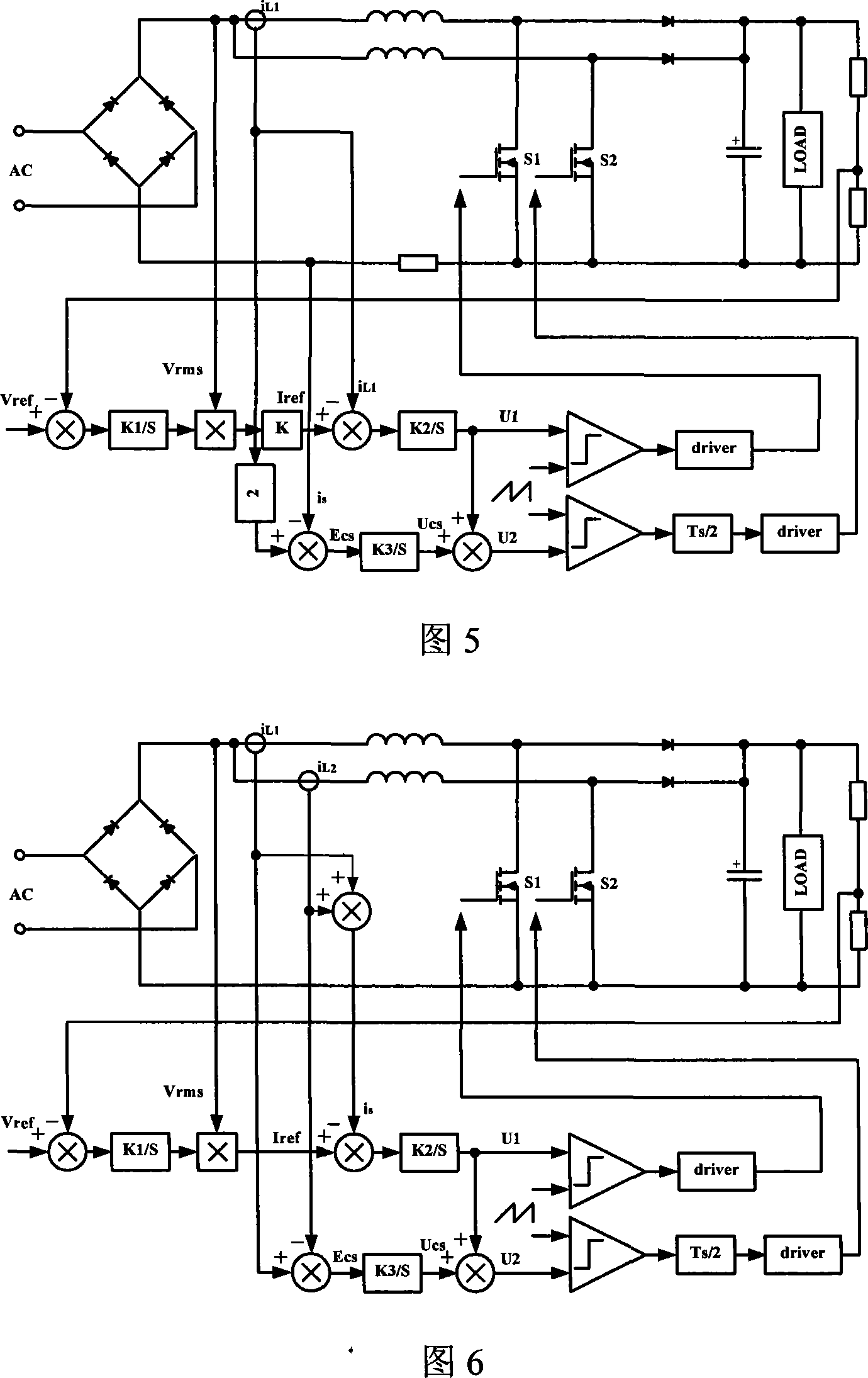
[0053] As shown in Figure 5, one difference between it and Embodiment 1 is that the difference of the inductor current is obtained by calculating the difference between the total current is and the inductor current of one of the step-up branches, specifically: sampling the first step-up The inductance current iL1 and the total current is of the circuit are used as the difference signal of the inductance current iL1 and iL2 of the first and second booster circuits through calculation (2×iL1-is) to participate in subsequent calculations, where is is equivalent to that in the first embodiment The sum of the two inductor currents (iL1+iL2), the result of the difference calculation (2×iL1-is) is equivalent to (iL1-iL2) in the first embodiment. Another difference between it and Embodiment 1 is: after the control signals Ua and Ub are sent to the comparison register, the phase shift of the control signal Ub is 180°.

[0054] Example three

[0055] As shown in Figure 6, the differenc...

Embodiment 4

[0057]As shown in FIG. 7 , the difference between it and Embodiment 1 is that the feedback current signal of the first step-up circuit is the total current signal is, and the difference of the inductor current is realized by calculating the total current and one of the inductor currents, specifically: Sampling the total current is as the current feedback signal of the first boost circuit, sampling the inductor current iL1 of the first boost circuit and calculating (2×iL1-is) as the first and second boost circuit inductor current iL1 and The difference signal of iL2 participates in subsequent operations, where is is equivalent to the sum of the two inductor currents (iL1+iL2) in Embodiment 1, and the result of the difference operation (2×iL1-is) is equivalent to (iL1 -iL2).


PUM


Abstract

The invention discloses a PFC circuit which is provided with an average current control module, comprising a first boosting circuit, a second boosting circuit and the average current control module. The average current control module comprises a sampling unit, a difference value operating unit, a proportion integral unit and a duty ratio regulating unit which are connected one by one. The duty ratio regulating unit realizes the average current of the inductance current mean in a switch cycle. The invention also discloses an average current control method used for the PFC circuit, and the method comprises the following steps: A. a reference current is produced; B. the current is sampled and the difference value is operated to obtain the inductance current difference value of two parallel branches; C. control signal one of the first boosting circuit is produced through operation; D. control signal two of the second boosting circuit is produced through operation; E. the duty ratio of the two branches is obtained by regulating the duty ratio.

Description

technical field [0001] The invention relates to a PFC (Power Factor Correction) circuit, in particular to a two-way parallel boosting PFC circuit with a current equalizing control module and a current equalizing control method thereof. technical background [0002] With the improvement of the power level of the power supply, the traditional single-phase boost PFC circuit is no longer suitable for the front-end rectification circuit of the high-power power supply. In the application occasions of high current and high power, multiple parallel Boost PFC circuits are often used. Since the interleaved multi-channel parallel Boost PFC circuit has the characteristics of small input current and output current ripple and small branch power level, it has been more and more widely used in medium and high-power power supplies. The multi-channel parallel Boost PFC circuit must not only ensure that the total input current is in phase with the rectified voltage, but also meet the requirem...

Claims


Application Information

Patent Timeline
IPC IPC(8): H02M1/42H02M1/14
CPCY02B70/126H02M2003/1586H02M1/4225Y02B70/10Y02P80/10H02M3/1586
Inventor 李茂华
Owner EMERSON NETWORK POWER CO LTD
Why Eureka
Try Eureka