
A non-integer frequency difference eliminator and phase-lock loop that can product non-integer real-time clock signal

A clock signal, non-integer technology, applied in the direction of pulse processing, pulse technology, power automatic control, etc., can solve the problem of unable to change multiple frequency division modes

Inactive Publication Date: 2010-12-29
SUNPLUS TECH CO LTD
View PDF5 Cites 0 Cited by
  • Summary
  • Abstract
  • Description
  • Claims
  • Application Information

AI Technical Summary

Problems solved by technology

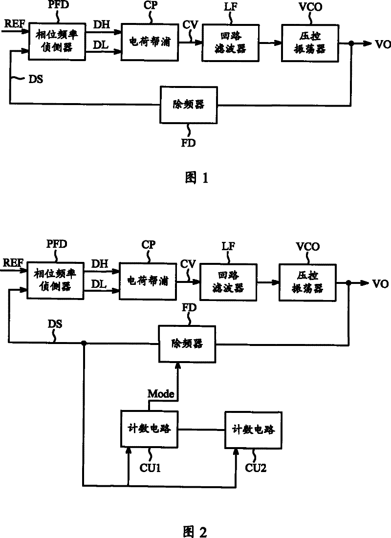
However, the multiple of the frequency of the oscillating clock signal VO output by the phase-locked loop has been limited between N and N+1
That is to say, the frequency division mode of the phase-locked loop under this type of architecture is only divided by N or N+1 double frequency division mode, and cannot be arbitrarily converted into multiple frequency division mode under the same architecture.

Method used


Image

  • A non-integer frequency difference eliminator and phase-lock loop that can product non-integer real-time clock signal
  • A non-integer frequency difference eliminator and phase-lock loop that can product non-integer real-time clock signal
  • A non-integer frequency difference eliminator and phase-lock loop that can product non-integer real-time clock signal

Examples


Embodiment Construction

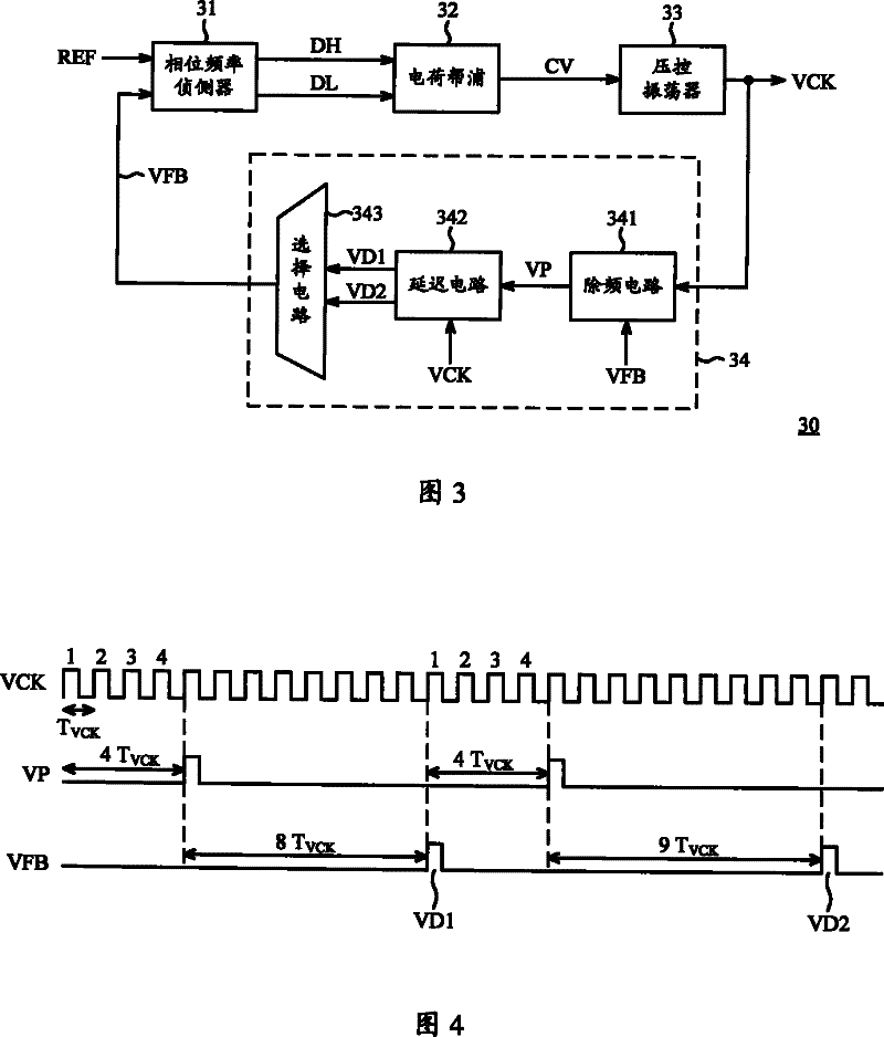
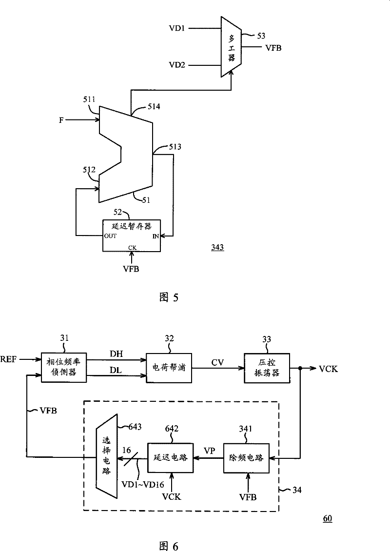
[0024] FIG. 3 is a circuit block diagram of a phase-locked loop 30 according to an embodiment of the present invention. Please refer to FIG. 3 , the PLL 30 includes a phase frequency detector 31 , a charge pump 32 , a voltage controlled oscillator 33 , and a non-integer frequency divider 34 . The non-integer frequency divider 34 includes a frequency dividing circuit 341 , a delay circuit 342 , and a selection circuit 343 . The coupling relationship among all components in the phase-locked loop 30 of this embodiment is shown in FIG. 3 . In addition, the following labels are also marked in FIG. 3 , which are respectively: the reference signal REF received by the phase frequency detector 31, the clock signal VCK output by the voltage-controlled oscillator 33, and the frequency division signal output by the frequency division circuit 341. The frequency pulse VP, the first delay pulse VD1 and the second delay pulse VD2 output by the delay circuit 342 , and the output pulse VFB fed...


PUM


Abstract

The invention relates to a non-integer frequency difference eliminator and a phase-lock control loop that can produce non-integer clock; wherein, the frequency difference eliminator comprises a frequency difference eliminating circuit, a delay circuit and an option circuit. The frequency difference eliminating circuit is used for leading a clock signal to be divided by an integer preset value so as to obtain a frequency difference eliminating impulse. The delay circuit is used for delaying a first preset multiple and a second preset multiple respectively of the circle of the frequency difference eliminating impulse so as to produce a first delay impulse and a second delay impulse. The option circuit chooses one of the first delay impulse and the second delay impulse according to the frequency difference eliminating multiple so as to be used for being taken as the output impulse of frequency difference eliminator; wherein, the frequency difference eliminating multiple is between the first preset multiple and the second preset multiple.

Description

technical field [0001] The present invention relates to a phase-locked loop technology, and in particular to a non-integer frequency divider and a phase-locked loop capable of generating non-integer clock signals. Background technique [0002] The function of the phase lock loop (Phase Lock Loop, PLL) is to use the oscillation source with a very low frequency variation as a reference, through the feedback function of the closed loop control system, to drive the action of the variable frequency element, so that it can quickly and continuously Stable and in phase with the oscillation source. [0003] FIG. 1 is a system architecture diagram of a known phase-locked loop. Please refer to Figure 1, the phase-locked loop is composed of five sub-circuit systems, namely: phase frequency detector PFD, charge pump CP, loop filter LF, voltage controlled oscillator VCO and frequency divider FD. The phase frequency detector PFD is used to detect the difference between the reference sign...

Claims


Application Information

Patent Timeline
Patent Type & Authority Patents(China)
IPC IPC(8): H03L7/18H03K5/135
Inventor 赵自强黄柏仁
Owner SUNPLUS TECH CO LTD
Learn More