Determination of the actual yaw angle and the actual slip angle of a land vehicle
A side-slip angle and yaw angle technology, which is applied to vehicle components, external condition input parameters, control devices, etc., can solve problems such as inappropriateness, expensive system, and lack of continuous guarantee of accuracy, and achieve the effect of improving accuracy
- Summary
- Abstract
- Description
- Claims
- Application Information
AI Technical Summary
Problems solved by technology
Method used
Image
Examples
Embodiment Construction
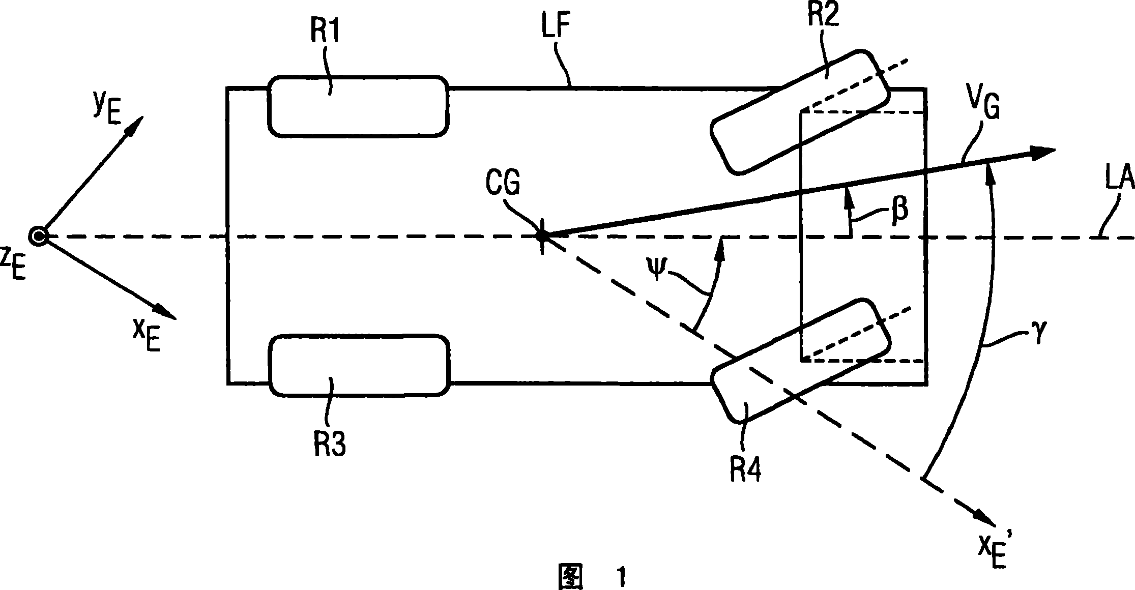
[0052] The simplified schematic diagram in FIG. 1 shows a general sketch of a land vehicle LF with two non-steerable wheels (rear axle) R1 and R3 and two steerable wheels (front axle) R2 and R4. Furthermore, the longitudinal axis LA of the vehicle and the center of gravity CG of the vehicle are shown. Here, a top view of the vehicle is shown with respect to a coordinate system fixed on the ground, which has the main axis X E , Y E and Z E , where the principal axis x E and Y E Stretch out a plane parallel to the ground on which the car moves and the third axis Z E Protrudes from the viewing plane and faces away from the viewer's direction. The plane of the car is here parallel to the ground (plane X E / Y E ) orientation, pitch angle θ and shimmy angle of the car This is set to zero. The current yaw angle ψ plotted with respect to the vehicle's center of gravity CG is thus parallel to the ground-fixed main axis X E Auxiliary spindle X passing through the car's center...
PUM
 Abstract
Description
Claims
Application Information
 - R&D
- Intellectual Property
- Life Sciences
- Materials
- Tech Scout
- Unparalleled Data Quality
- Higher Quality Content
- 60% Fewer Hallucinations
Browse by: Latest US Patents, China's latest patents, Technical Efficacy Thesaurus, Application Domain, Technology Topic, Popular Technical Reports.
© 2025 PatSnap. All rights reserved.Legal|Privacy policy|Modern Slavery Act Transparency Statement|Sitemap|About US| Contact US: help@patsnap.com


