

Refrigeration apparatus
A refrigeration device and refrigerant technology, which is applied to household refrigeration devices, refrigerators, refrigeration components, etc.
- Summary
- Abstract
- Description
- Claims
- Application Information
AI Technical Summary
Problems solved by technology
Method used
Image

Examples
no. 1 example 》
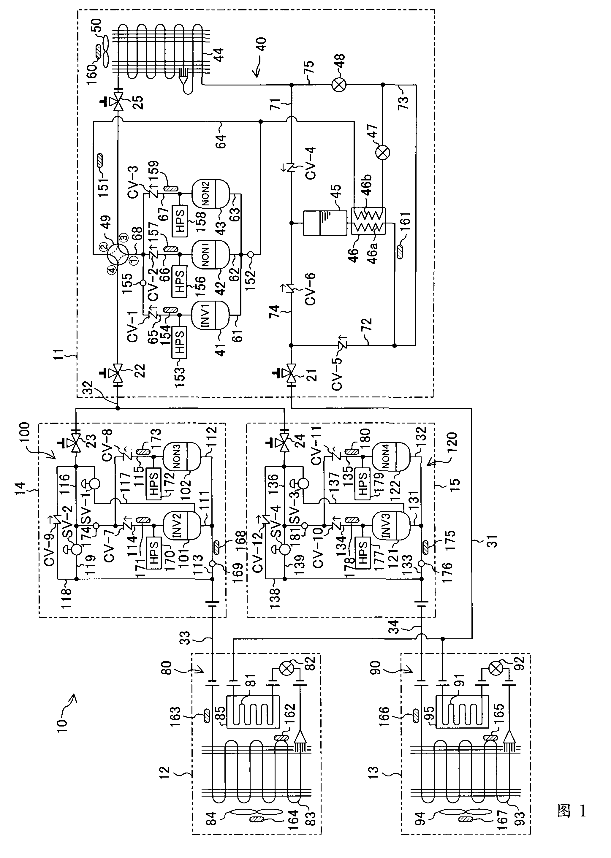
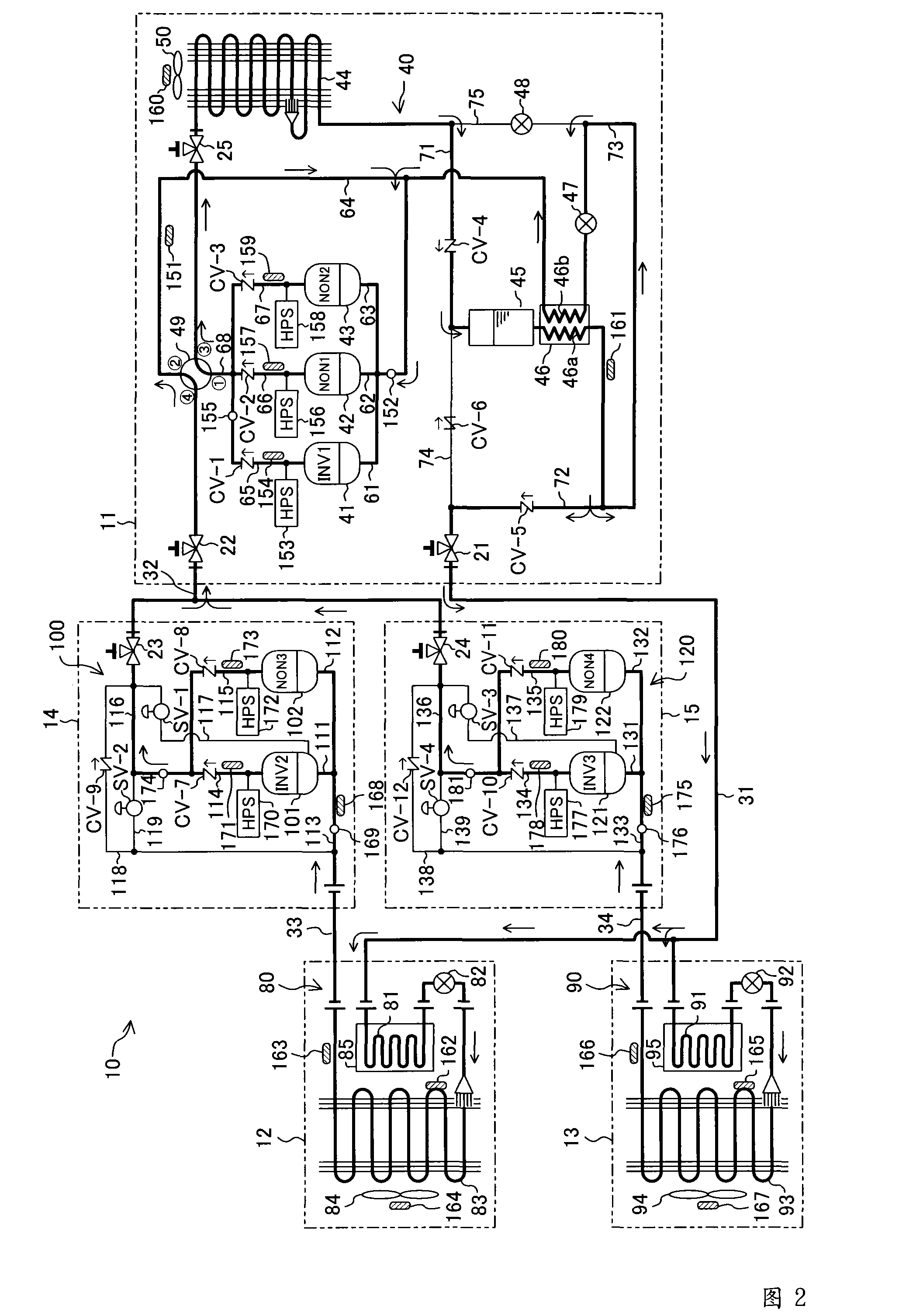
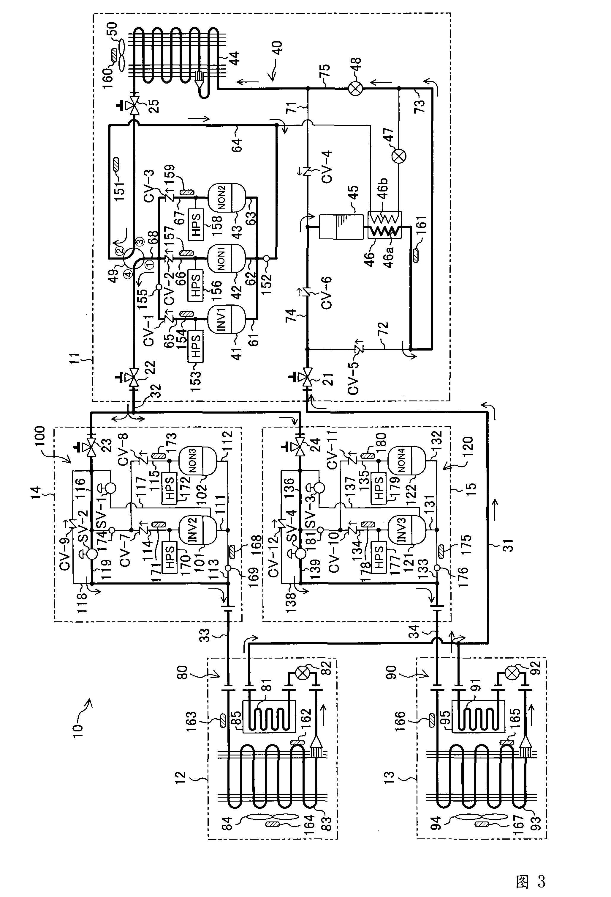
The refrigerating apparatus 10 of the first embodiment is installed in a convenience store or the like to cool a plurality of freezers.
[0055] As shown in FIG. 1 , the refrigerating device 10 of the first embodiment has an outdoor unit 11 , a first refrigerated showcase 12 , a second refrigerated showcase 13 , a first booster unit 14 and a second booster unit 15 . The outdoor unit 11 is installed outdoors. On the other hand, the other units 12, 13, 14, and 15 are installed in stores such as convenience stores.
[0056] The outdoor unit 11 is provided with an outdoor circuit 40, the first refrigerated showcase 12 is provided with a first refrigerated circuit 80, the second refrigerated showcase 13 is provided with a second refrigerated circuit 90, and the first booster unit 14 is provided with a A supercharging circuit 100 is provided with a second supercharging circuit 120 in the second supercharging unit 15 . In this refrigerating apparatus 10, these circuits 40, 80, 90, 1...
no. 2 example 》
The refrigeration system 10 of the second embodiment is different from the above-mentioned first embodiment in the structure of the refrigerant circuit 20 and the operation of the defrosting operation. Differences from the first embodiment described above will be described below.
[0121]As shown in FIG. 4 , the refrigerant circuit 20 of the second embodiment is provided with two liquid injection pipes 190 , 192 . One end of the first liquid injection pipe 190 is connected between the first cooling heat exchanger 83 of the first refrigeration circuit 80 and the first indoor expansion valve 82 . On the other hand, the other end of the first liquid injection pipe 190 is connected to the first low-stage suction pipe 113 of the first booster circuit 100 . The first liquid injection pipe 190 is provided with a first liquid injection valve 191 . The first liquid injection valve 191 is composed of an electronic expansion valve whose opening degree can be adjusted. Furthermore, one ...
no. 3 example 》
The refrigeration device 10 of the third embodiment is different from the above-mentioned first embodiment and the second embodiment in the structure of the booster units 14 , 15 . Differences from the first and second embodiments described above will be described below.
[0141] As shown in FIG. 6 , in the first booster circuit 100 of the first booster unit 14 , a first oil separator 143 is provided on the discharge side of the second inverter compressor 101 and the third fixed frequency compressor 102 . Similarly, in the second booster circuit 120 of the second booster unit 15 , a second oil separator 144 is provided on the discharge side of the third inverter compressor 121 and the fourth fixed frequency compressor 122 .
[0142]As shown in FIG. 7 , each of the oil separators 143 and 144 is constituted by a so-called demister type oil separator. Each of the oil separators 143 and 144 has an airtight oil recovery container 145 and a demister 146 . Each oil recovery containe...
PUM
 Abstract
Description
Claims
Application Information