
Device and method for on-line switching uninterrupted power supply

A power supply and intermediate relay technology, which is applied in circuit devices, battery circuit devices, emergency power supply arrangements, etc., can solve the impact of continuous power supply in power outage mode, cannot meet the needs of emergency repair of UPS device failures, and regularly test requirements for offline maintenance functions. Electricity demand and other issues to achieve the effect of reducing the failure rate

Active Publication Date: 2008-07-16
BAOSHAN IRON & STEEL CO LTD
View PDF0 Cites 20 Cited by
  • Summary
  • Abstract
  • Description
  • Claims
  • Application Information

AI Technical Summary

Problems solved by technology

The disadvantage of this type of configuration is that it cannot meet the needs of UPS device failure emergency repair, offline maintenance function and device periodic test requirements. When the UPS device is abnormal or faulty, only power outage processing will be performed, which will affect the continuous power demand of these important users.
The power outage mode during the periodical maintenance and function test of the UPS unit also has an impact on the continuous power supply of these users
[0003] In the prior art, there is no relevant technology that solves the problem of emergency repair when the UPS device is abnormal and the problem of power failure to the load during regular maintenance

Method used


Image

  • Device and method for on-line switching uninterrupted power supply
  • Device and method for on-line switching uninterrupted power supply
  • Device and method for on-line switching uninterrupted power supply

Examples


Embodiment Construction

[0021] The technical scheme of the present invention will be further described below in conjunction with the drawings and embodiments.

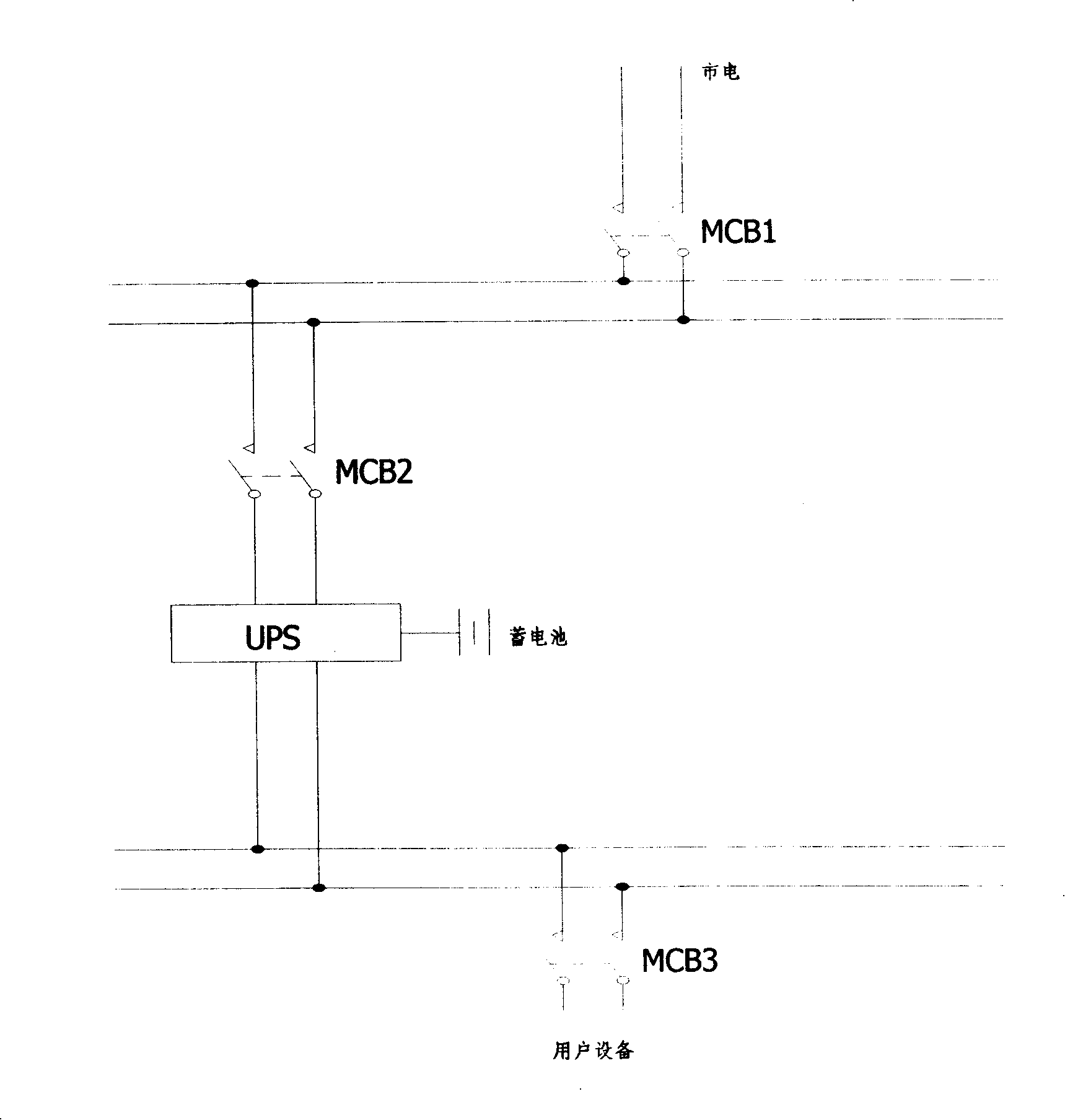
[0022] The purpose of the present invention is to provide a technology for online switching UPS. First, refer to figure 1 , figure 1 It is the electrical schematic diagram of the UPS power supply circuit in the prior art. The input end of the UPS is connected to the input power supply circuit through the UPS device input power switch MCB2, and the input power supply circuit is connected to the mains line through the power supply line switch MCB1. The output of the UPS The terminal is connected to the output power supply circuit, and the user equipment is connected to the output power supply circuit through the user load switch MCB3. Thus, the circuit loop for supplying power to the user equipment is: mains (220V or 380V) → power supply line switch MCB1 → UPS device input power switch MCB2 → UPS → user load switch MCB3 → user equipment. In the p...


PUM


Abstract

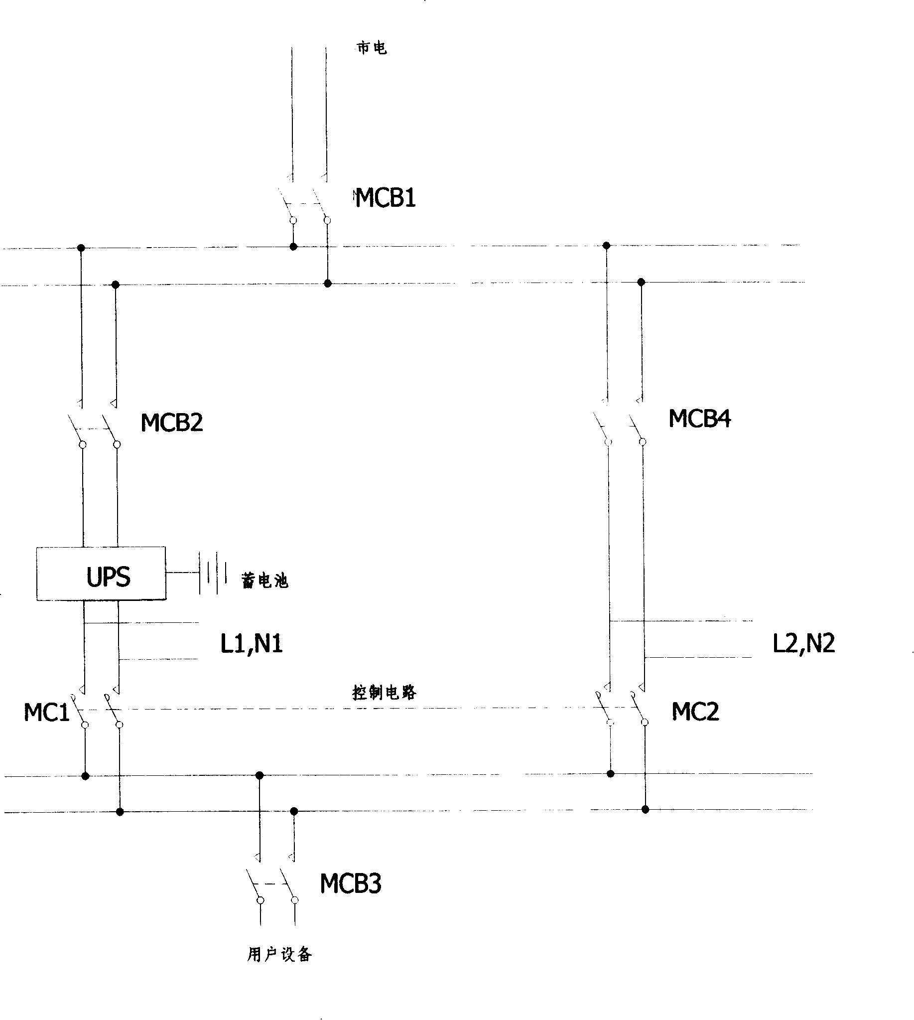
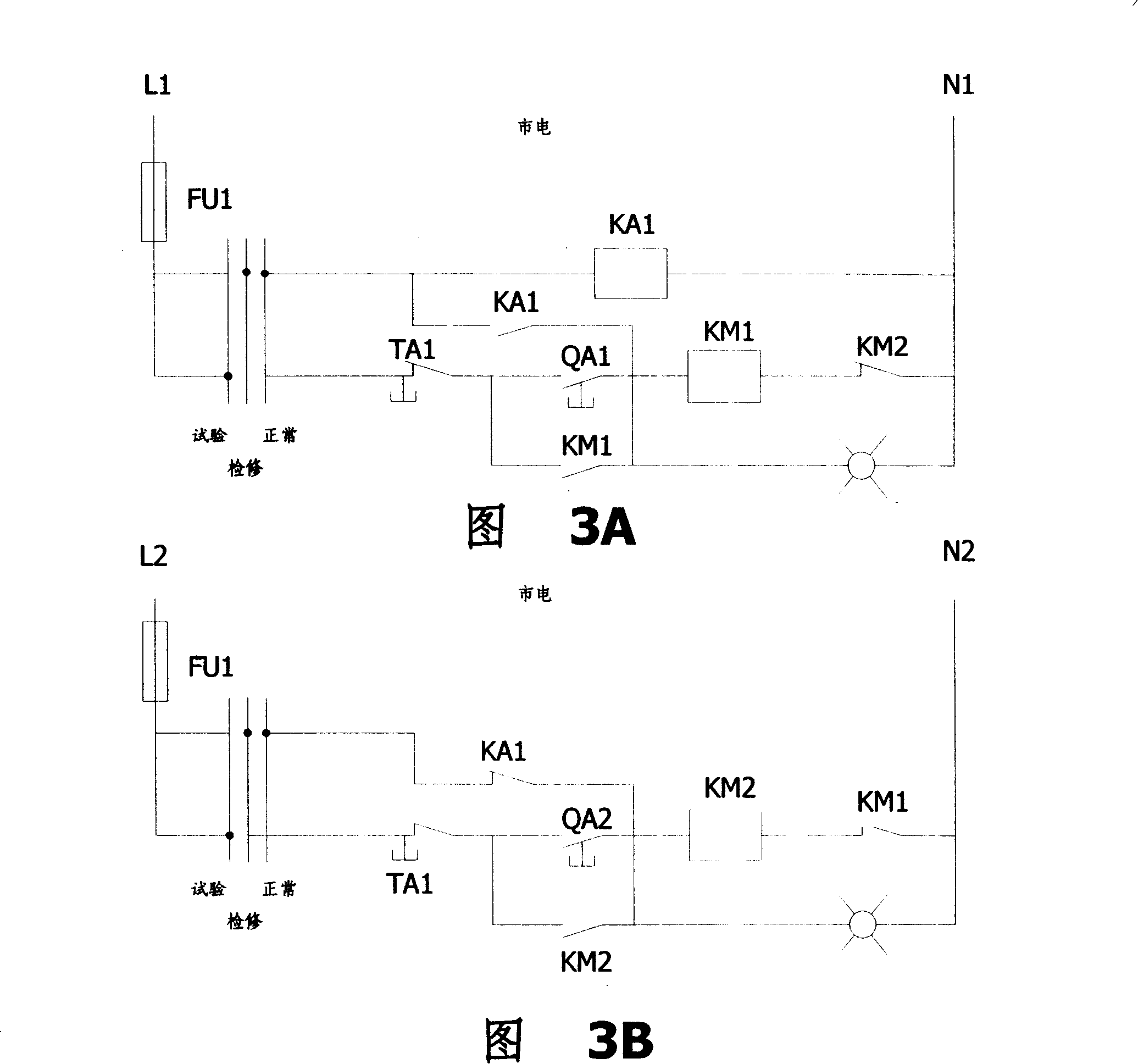
The invention discloses an on-line switching UPS device and a method thereof. An input terminal of the UPS is connected to an input power supply loop through inputting a power switch MCB2 by the UPS device, wherein, the input power supply loop is connected to the commercial power circuit through a supply line switch MCB1, an output terminal of the UPS is connected to an output power supply loop, a user facility is connected to the output power supply loop by a user load switch MCB3. The device also comprises an outer shunt circuit connected in parallel with the UPS and a set of contactors, wherein, the outer shunt circuit is connected to the input power supply loop by an outer shunt circuit switch MCB4 and is connected with the output power supply loop; a first main contact point MC1 is connected in series between the output terminal of the UPS and the output power supply loop, a second main contact point MC2 is connected in series between the outer shunt circuit switch MCB4 and the output power supply loop; the contactors are switched between the UPS and the outer shunt circuit. The technical proposal of the invention realizes that the switching way of the controller is controlled by the joint point of a relay by adopting a small number of elements such as the set of controllers, the relay and the switch and basically realizes the very quick switching. Therefore, the invention is an economic and effective UPS on-line switching mode.

Description

Technical field [0001] The present invention relates to power system equipment, and more specifically, to a device and method for online switching of uninterrupted power supplies. Background technique [0002] Loads that use uninterruptible power supply (UPS) power supply are generally important users who cannot be powered off and have high power quality requirements. At present, in the power supply circuits of UPS devices at home and abroad, in addition to the UPS power supply mode when there is a normal power supply mode, there is also an internal bypass device when the power grid fails, abnormal or internal component failure of the device, the purpose of which is mainly to protect the inside of the device The components are not damaged, such as: when the voltage and frequency indicators of the power supply system exceed their ratings, and the rectifier or inverter module components in the device are abnormal or faulty, switch to the internal bypass. The disadvantage of this ty...

Claims


Application Information

Patent Timeline
Patent Type & Authority Applications(China)
IPC IPC(8): H02J7/00H02J9/06
Inventor 李关定练大胜傅金华陈忠平
Owner BAOSHAN IRON & STEEL CO LTD
Learn More