
Forme location fixtures and computer direct forme maker having the same

A technology for positioning fixtures and plate making machines. It is applied in the directions of plate preparation, printing, and shim devices. It can solve the problems of inaccurate positioning and deviation of the printing plate, and achieve the consistency, avoid skew and accurate positioning. Effect

Inactive Publication Date: 2008-07-23
北人集团有限公司
View PDF0 Cites 0 Cited by
  • Summary
  • Abstract
  • Description
  • Claims
  • Application Information

AI Technical Summary

Problems solved by technology

In the positioning method adopted by the existing CTP (computer-to-plate-making machine), as long as the printing plate is in contact with any position on the cylindrical pin, it means that the printing plate is installed in place. Therefore, the positioning is not very accurate, and the output printing plate on the plate-making machine will have deviations.

Method used


Image

  • Forme location fixtures and computer direct forme maker having the same
  • Forme location fixtures and computer direct forme maker having the same
  • Forme location fixtures and computer direct forme maker having the same

Examples


Embodiment Construction

[0056] Below in conjunction with accompanying drawing, structural principle and working principle of the present invention are specifically described:

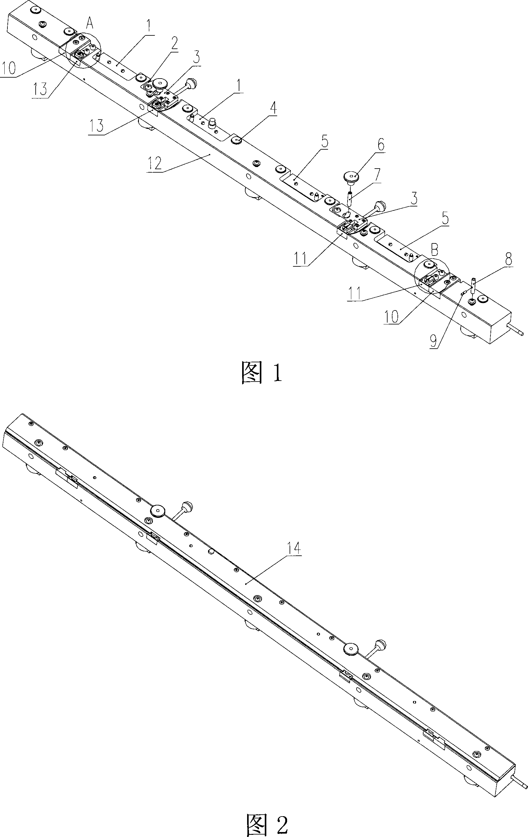
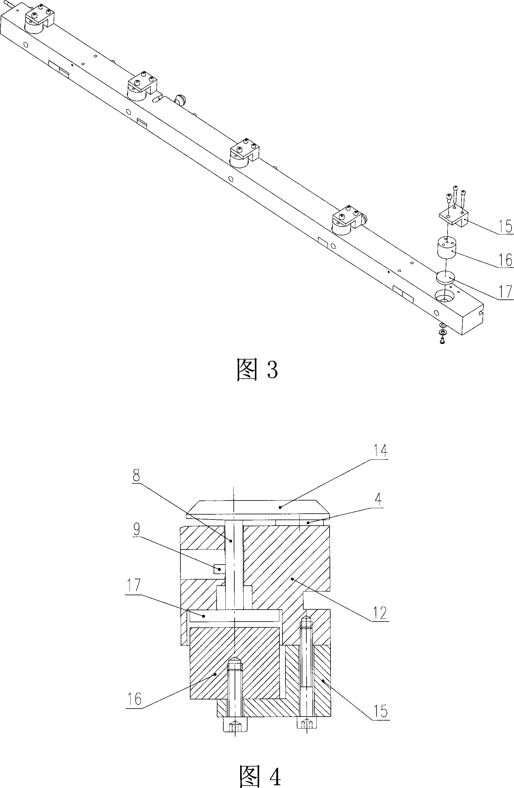
[0057] Please refer to Figure 1 the installation diagram of the printing plate positioning fixture parts; Figure 2 the top assembly drawing of the printing plate positioning fixture; Figure 3 the bottom installation diagram of the printing plate positioning fixture.

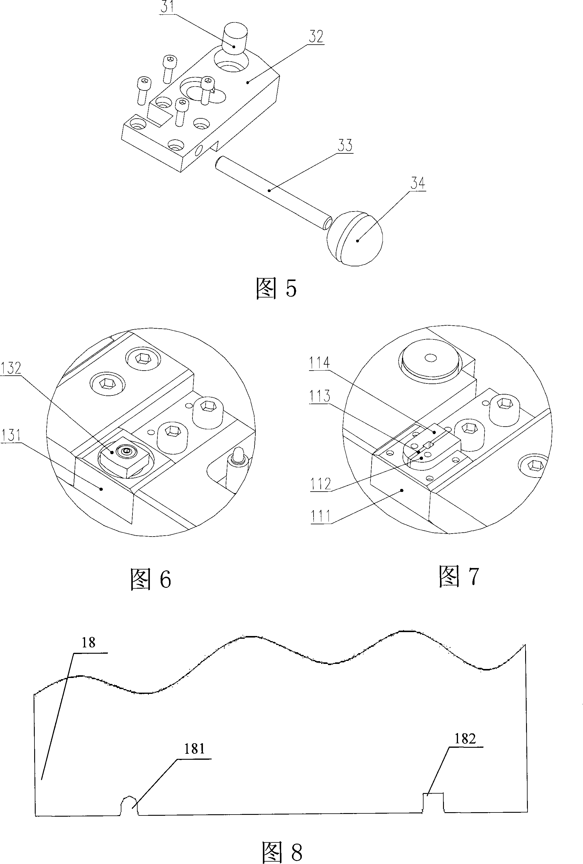
[0058] In the specific embodiment shown in the figure, the present invention comprises: substrate 12, U-shaped locating pin device 11, square locating pin device 13, circuit board 1, circuit board 5, top plate 14 and by electromagnet fixing seat 15, electromagnet 16. The clamping device formed by the tray 17 and the pull rod 8 .

[0059]Two sets of locating pin devices consisting of a left U-shaped locating pin device 11 and a right square locating pin device 13 are arranged on the substrate 12, wherein the group adjacent to the edge is a fixed locating pin devic...


PUM


Abstract

The invention provides a forme location fixture which is arranged on a platemaker, comprising a basal body and at least two group of positioning pin devices; each group is symmetrically arranged on the basal body; wherein, one group of positioning pin device which is adjacent to the edge of the basal body is a fixed positioning pin device and the other positioning pin devices are movable positioning pin devices; the invention also comprises a plurality group of clamping devices which are arranged on the basal body, and a position detection circuit board which is arranged on the basal body and corresponding to each positioning pin device; the position detection circuit board comprises an indicating device, a position detection circuit, an indicating on / off circuit, and a clamping on / off circuit; when misaligned location of the forme is detected by the position detection circuit, the indicating on / off circuit controls the indicating device to emit an instruct; when the aligned location of the forme is detected by the position detection circuit, the clamping on / off circuit controls the clamping device to clamp the forme. When the location fixture which is provided by the invention is applied to a computer direct platemaker, the location is exact, the inclined forme phenomenon is avoided, the consistency of the output forme on the platemaker is ensured, and the invention can be suitable for the forme location with different specifications.

Description

technical field [0001] The invention relates to the field of printing equipment, in particular to a printing plate positioning jig in computer-to-plate making equipment. Background technique [0002] The computer-to-plate-making machine needs to position the printing plate first during the plate-making process, and then clamp the printing plate after the positioning is completed, so that all the printing plates produced on the machine are fixed at the same position, and the same reference is used for the printing plate on the subsequent printing machine. The overprinting provides the necessary accuracy guarantee. [0003] There are usually two positioning methods, one is to rely on three-point positioning, two points on the front end of the printing plate, and one point on the side; the other is the U-shaped slot positioning method. In the positioning method adopted by the existing CTP (computer-to-plate-making machine), as long as the printing plate is in contact with any ...

Claims


Application Information

Patent Timeline
Patent Type & Authority Applications(China)
IPC IPC(8): B41C1/00B41N6/00
Inventor 李小富李强潘玲珍张跃明徐相涛林媛媛刘向明
Owner 北人集团有限公司
Learn More