Supercharge Your Innovation With Domain-Expert AI Agents!

Suction channel of fiber bundle unit

A technology of fiber bundles and channels, applied in the field of fiber bundles, can solve the problems of high cost of use, reduce air consumption, and avoid changes in the direction of rotation

Inactive Publication Date: 2012-02-15
MASCHINENFABRIK RIETER AG
View PDF1 Cites 0 Cited by
  • Summary
  • Abstract
  • Description
  • Claims
  • Application Information

AI Technical Summary

Problems solved by technology

Due to the enlarged starting area of ​​the suction slot, the fan has a very high energy requirement, which makes the use of fiber bundling devices with such a suction channel expensive

Method used


Image

  • Suction channel of fiber bundle unit
  • Suction channel of fiber bundle unit
  • Suction channel of fiber bundle unit

Examples


Embodiment Construction

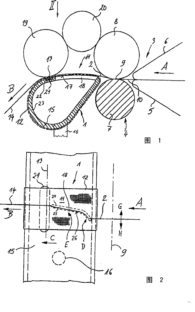
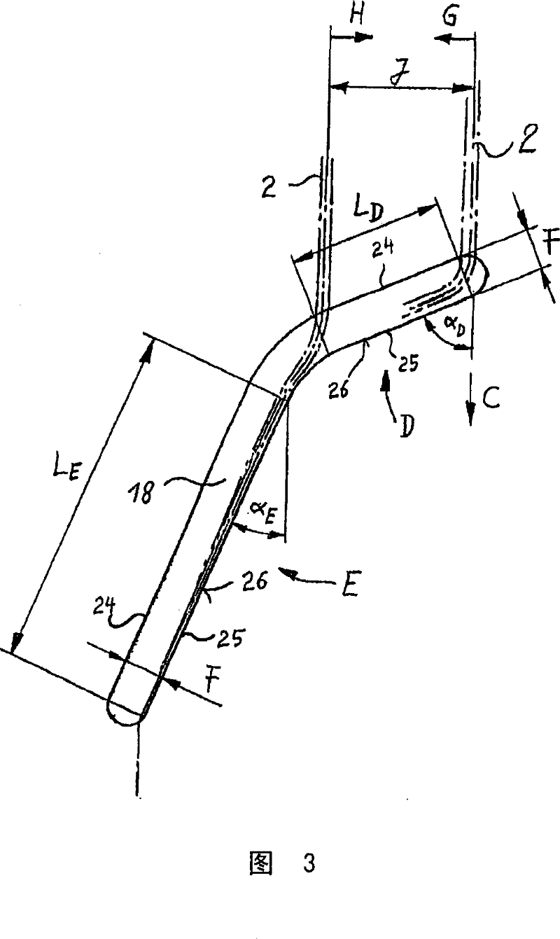
[0020] exist figure 1 and figure 2 A fiber bundle device 1 for compressing a fiber sliver 2 of short fibers is shown in FIG. 2 , which is arranged downstream of a only partly shown drafting unit 3 of a weaving machine. The weaving machine, which can be, for example, a ring spinning machine, usually has a plurality of drafting units 3 arranged side by side. Only the front pair of drafting rollers 4 and the upstream small belt pairs 5, 6 are shown in this drafting mechanism 3, which is designed in a known manner.

[0021] The front drafting roller pair 4 comprises driven bottom rollers 7, which can be configured as bottom rollers passing in the longitudinal direction of the machine, and each drafted fiber sliver is assigned a hold-down roller 8. The bottom roller 7 and the pressure roller 8 together form a front nip line 9 which ends the drafting zone of the drafting mechanism 3 . The fiber web or alternatively the roving 10 is fed to the drafting device 3 along the conveyin...


PUM

PropertyMeasurementUnit
widthaaaaaaaaaa
widthaaaaaaaaaa

Abstract

A suction channel for a fiber bundling device arranged downstream of a drafting device for the coarse fiber strand has a tubular base body, the outer contour of which contains a sliding surface for an air-permeable conveyor belt. At least one suction slot bounded by two sides is provided and extends substantially in the peripheral direction of the basic body. Only one side of the suction slot forms the fiber guide edge. The fiber guide edge comprises at least two regions which have different angles of inclination with respect to the circumference of the main body. The suction slot has a substantially constant width along the fiber guide edge.

Description

technical field [0001] The invention relates to a suction channel with a tubular base body for a fiber bundling device arranged after a drafting mechanism of a coarse fiber strand, the outer contour of which contains a sliding surface for an air-permeable conveyor belt, in which at least one Suction slot delimited by two sides, which extends substantially in the peripheral direction of the main body, wherein only one side of the suction slot forms a fiber guide edge comprising at least two regions , which have different inclination angles with respect to the circumference of the substrate. Background technique [0002] For the fiber strands that leave the drafting mechanism under pneumatic compression in the fiber bundle device, it is characterized in that the fiber strands are laid flat in the compression zone in the compression zone with fibers that are not yet twisted. The conveying element is conveyed, and in the compression zone an air flow is generated through the con...

Claims


Application Information

Patent Timeline
Patent Type & Authority Patents(China)
IPC IPC(8): D01H5/72
CPCD01H5/72
Inventor N·布伦克W·莱纳
Owner MASCHINENFABRIK RIETER AG
Features
  • R&D
  • Intellectual Property
  • Life Sciences
  • Materials
  • Tech Scout
  • Unparalleled Data Quality
  • Higher Quality Content
  • 60% Fewer Hallucinations
Learn More