
Direct current switch power supply control circuit

A technology of power control circuit and control circuit, which is applied in the direction of control/regulation system, conversion of DC power input to DC power output, electrical components, etc., which can solve the problem of increased circuit output voltage ripple, narrow error amplifier bandwidth, and slow circuit response speed And other problems, to achieve the effect of smooth conversion, reducing the range of change, and simple circuit design

Inactive Publication Date: 2008-07-23
VIMICRO CORP
View PDF0 Cites 28 Cited by
  • Summary
  • Abstract
  • Description
  • Claims
  • Application Information

AI Technical Summary

Problems solved by technology

[0013] (1) In the prior art, when the square wave input to the logic drive unit is switched between the maximum duty cycle mode and the 100% duty cycle mode, the ripple of the circuit output voltage increases significantly
[0014] (2) V EAO The range of change is very large. Due to the narrow bandwidth of the error amplifier, it takes a long time to respond to this large range of change, resulting in a relatively slow response speed of the circuit.
[0015] (3) When the circuit switches between the maximum duty cycle mode and the 100% duty cycle mode, the square wave input to the logic drive unit has an obvious state change, which is easily affected by noise and unstable

Method used


Image

  • Direct current switch power supply control circuit
  • Direct current switch power supply control circuit
  • Direct current switch power supply control circuit

Examples


Embodiment Construction

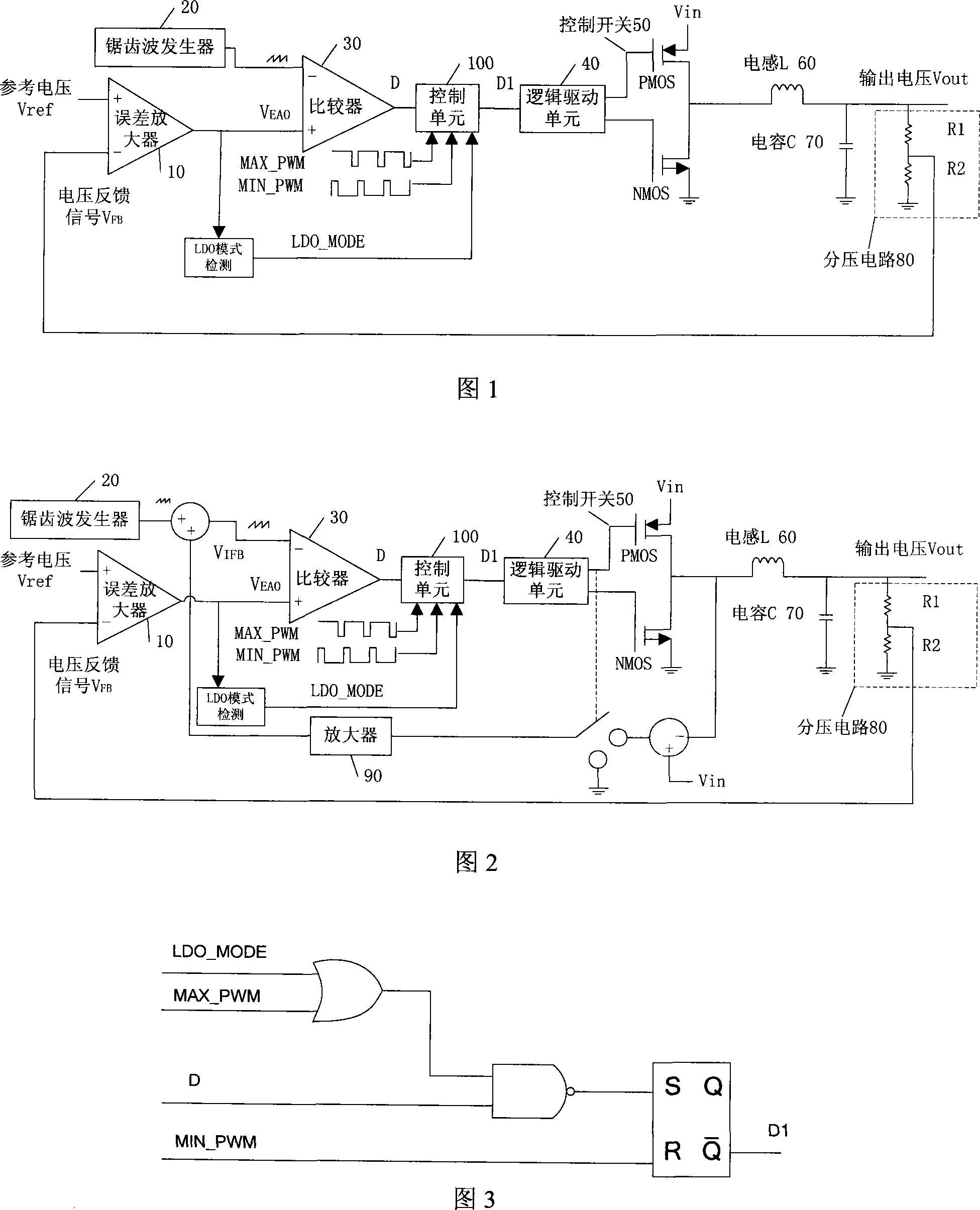
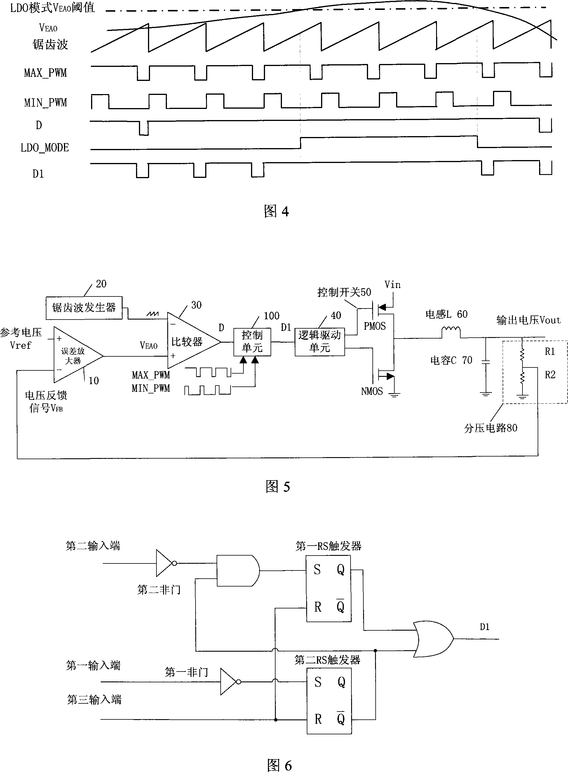
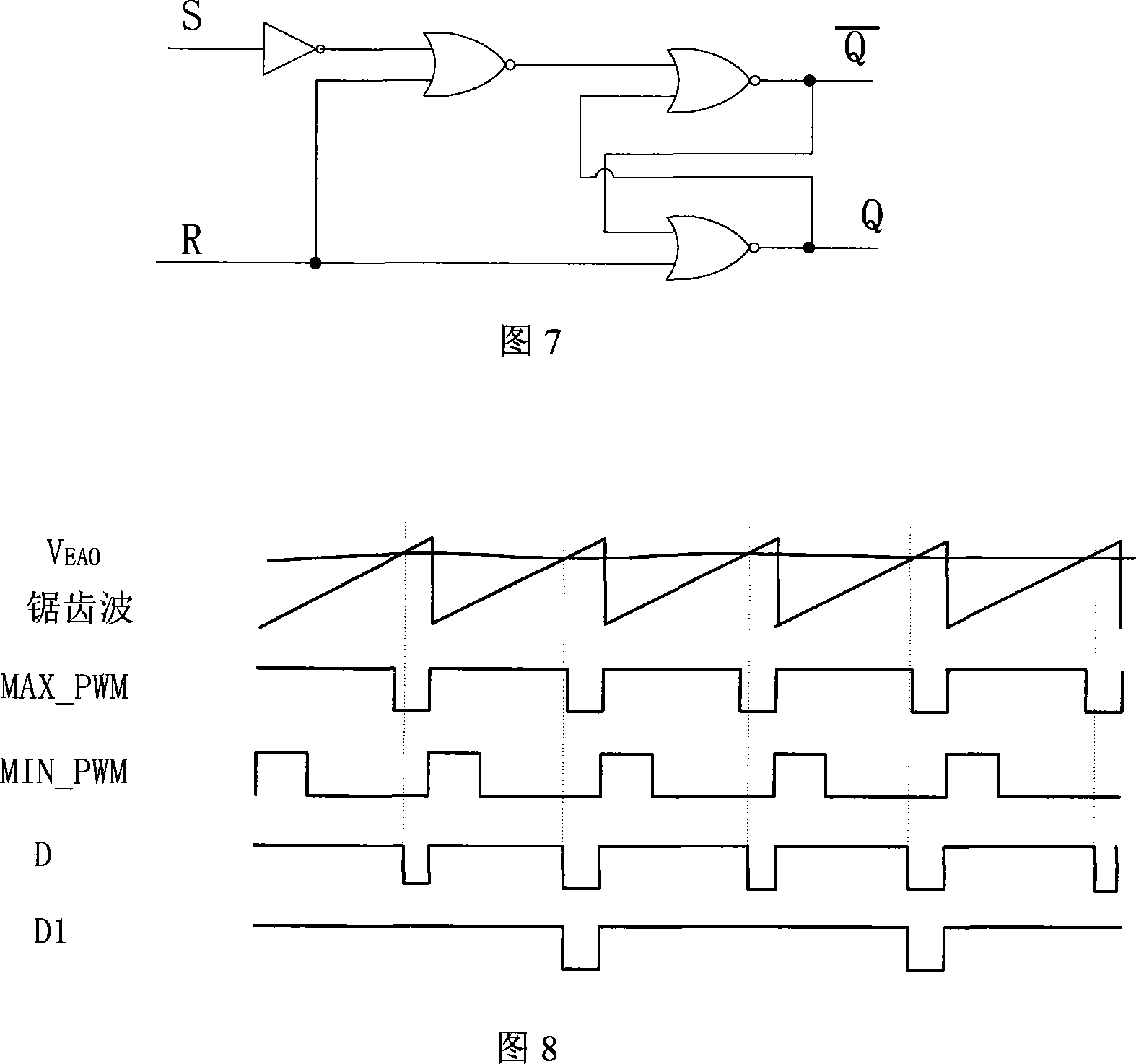
[0040] The invention improves the control unit circuit of the power supply control circuit, and the control unit outputs a square wave with a 100% duty ratio when the duty ratio of the square wave output by the input pulse width modulation comparator is greater than the maximum duty ratio of the circuit; When the duty ratio of the square wave output by the PWM comparator is less than or equal to the maximum duty ratio, the output is the same as the square wave output by the PWM comparator, thereby controlling the switching circuit in time according to V EAO Changes in the switch control, reducing the V EAO The range of change, thereby improving the response speed of the circuit, and reducing the output ripple of the output voltage when the circuit is converted from the maximum duty cycle mode to the 100% duty cycle mode.

[0041] As shown in FIG. 5 , the DC switching power supply control circuit of the present invention does not include an LDO mode detection module, and its co...


PUM


Abstract

The invention discloses a direct current switch power supply controlling circuit, which comprises a pulse-width modulating comparator, a controlling unit and a logic driving unit which are connected in turn, wherein output square-wave signals of the pulse-width modulating comparator are input in a first input end of the controlling unit, maximum duty cycle square-wave signal is input in a second input end, the output end is connected with the input end of the logic driving unit, when the duty cycle of output square-wave of the pulse-width modulating comparator which is input is lager than the maximum duty cycle, the controlling outputs the square-wave with 100% duty cycle. The direct current switch power supply controlling circuit realizes smooth conversion from the maximum duty cycle to 100% duty cycle through improving the controlling unit circuit of a power supply controlling circuit, which increases respond speed of the circuit, reduces ripple of output voltage in the process of conversation of the circuit from the maximum duty cycle mode to 100% duty cycle mode, the design of the circuit is simple, and the cost of circuit reconstruction is saved.

Description

technical field [0001] The invention relates to the technical field of electronic circuits, in particular to a DC switching power supply control circuit. Background technique [0002] The DC control switching power supply control circuit mainly includes a pulse-width modulation (Pulse-width Modulation, hereinafter referred to as pulse-width modulation or PWM) comparator, a control switch and an output LC circuit. The PWM comparator is used to compare the input signals at its input terminals to generate different duty Compared with the square wave signal, the square wave signal generated by the PWM comparator is used to drive the closing and closing of the control switch. The control switch is used to connect the input voltage to the LC circuit when it is closed, and cut off the The connection of the input voltage to and release of the energy of the LC circuit comprising an inductor connected to a control switch and a capacitor in series with the inductor, the node voltage of...

Claims


Application Information

Patent Timeline
Patent Type & Authority Applications(China)
IPC IPC(8): H02M3/156G05F1/56
Inventor 董贤辉王钊尹航杨喆
Owner VIMICRO CORP
Learn More