Drum type drying and washing machine

A washing and drying machine, drum-type technology, applied to other washing machines, washing machines with containers, household clothes dryers, etc., can solve the problems such as the air supply capacity of the blower 31 drops, and achieve the effect of removing blockage

Inactive Publication Date: 2008-07-23
SHARP KK
View PDF1 Cites 10 Cited by
  • Summary
  • Abstract
  • Description
  • Claims
  • Application Information

AI Technical Summary

Problems solved by technology

[0014] Usually, in the washing process or the rinsing process, foreign matter such as lint in the washing water is removed by a filter unit (not shown) provided before the drain valve 20, but in the drying process, the air passing through the drying unit 24 is not carried out. And the removal of the ...

Method used


Image

  • Drum type drying and washing machine
  • Drum type drying and washing machine
  • Drum type drying and washing machine

Examples


no. 1 approach

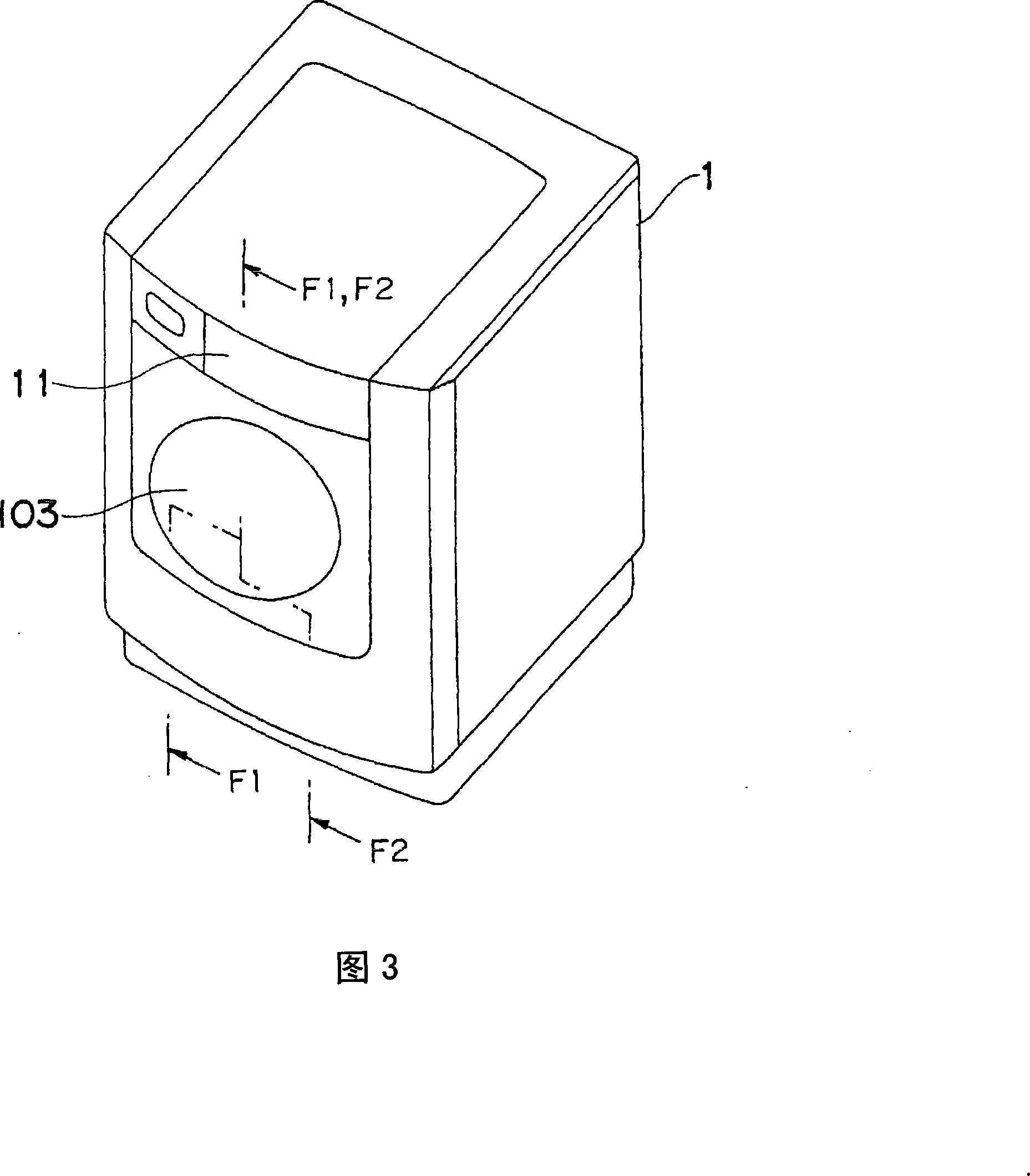
[0144] Fig. 3 is an external perspective view of the drum-type washing and drying machine according to the first embodiment of the present invention. While covering the outer periphery with the outer case 1, this drum type washing and drying machine has an outer case opening 111 (see FIG. The mechanism is rotatably mounted on the outer case 1 . In addition, reference numeral 11 in FIG. 3 is an operation panel.

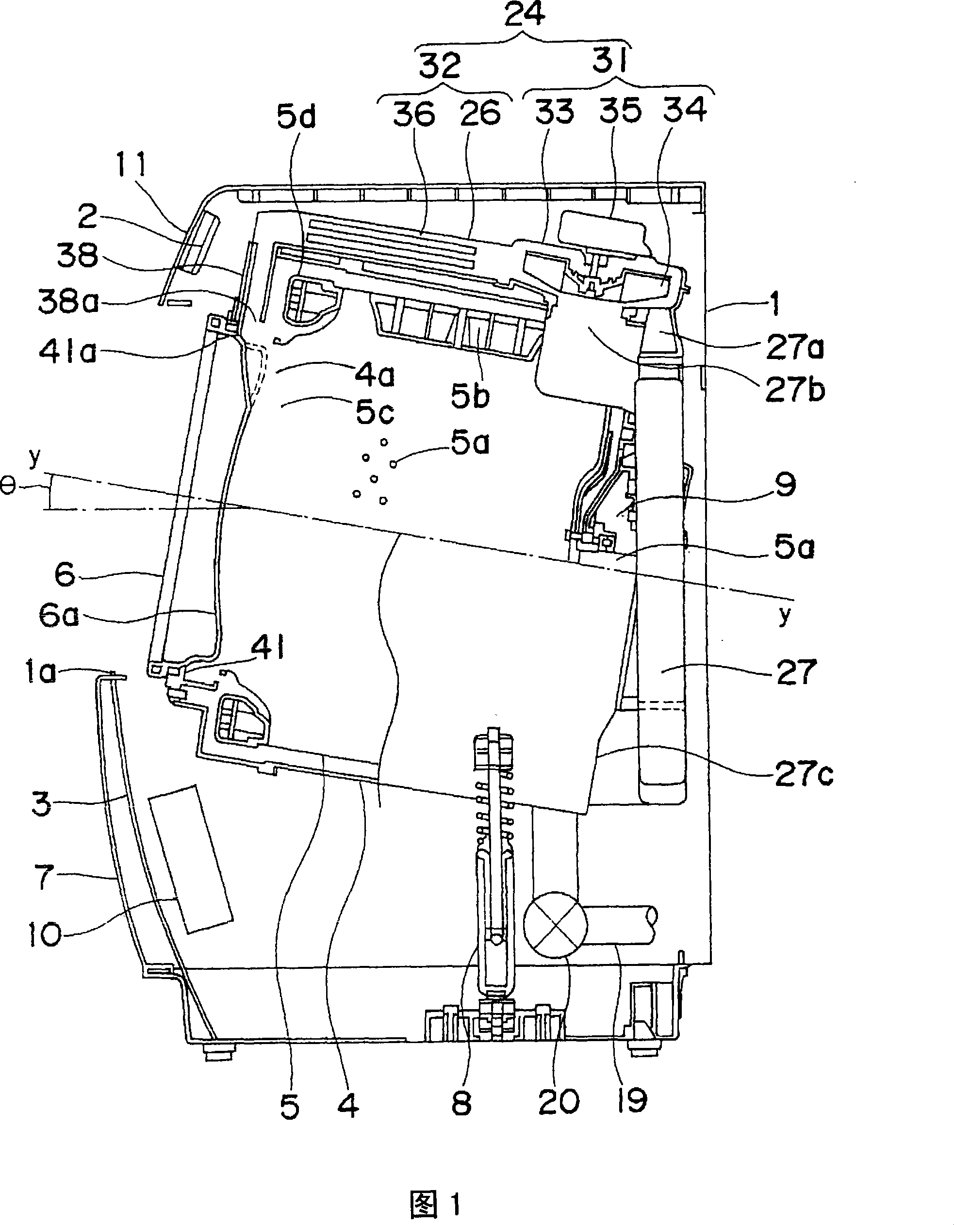
[0145] FIG. 4 shows a schematic sectional view viewed from line F1 - F1 in FIG. 3 .

[0146] An outer case opening 111 is formed on the front surface of the outer case 1 . The outer case opening 111 is opened and closed by the door 103 that is rotatable relative to the outer case 1 as described above. In addition, the operation panel 11 having operation keys and a display portion is provided on the front upper portion of the outer case 1 . On the back side of the operation panel 11 (on the side of the water tank 4 ), the control unit 2 for controlling the operation...

no. 2 approach

[0190] Fig. 13 is an external perspective view of a drum-type washing and drying machine X according to a second embodiment of the present invention. This drum type washing and drying machine X covers the outer periphery with the outer case 1, and has an outer case opening 111 (refer to FIG. The hinge mechanism is rotatably installed on the outer case 1 . In addition, reference numeral 11 in FIG. 3 is an operation panel.

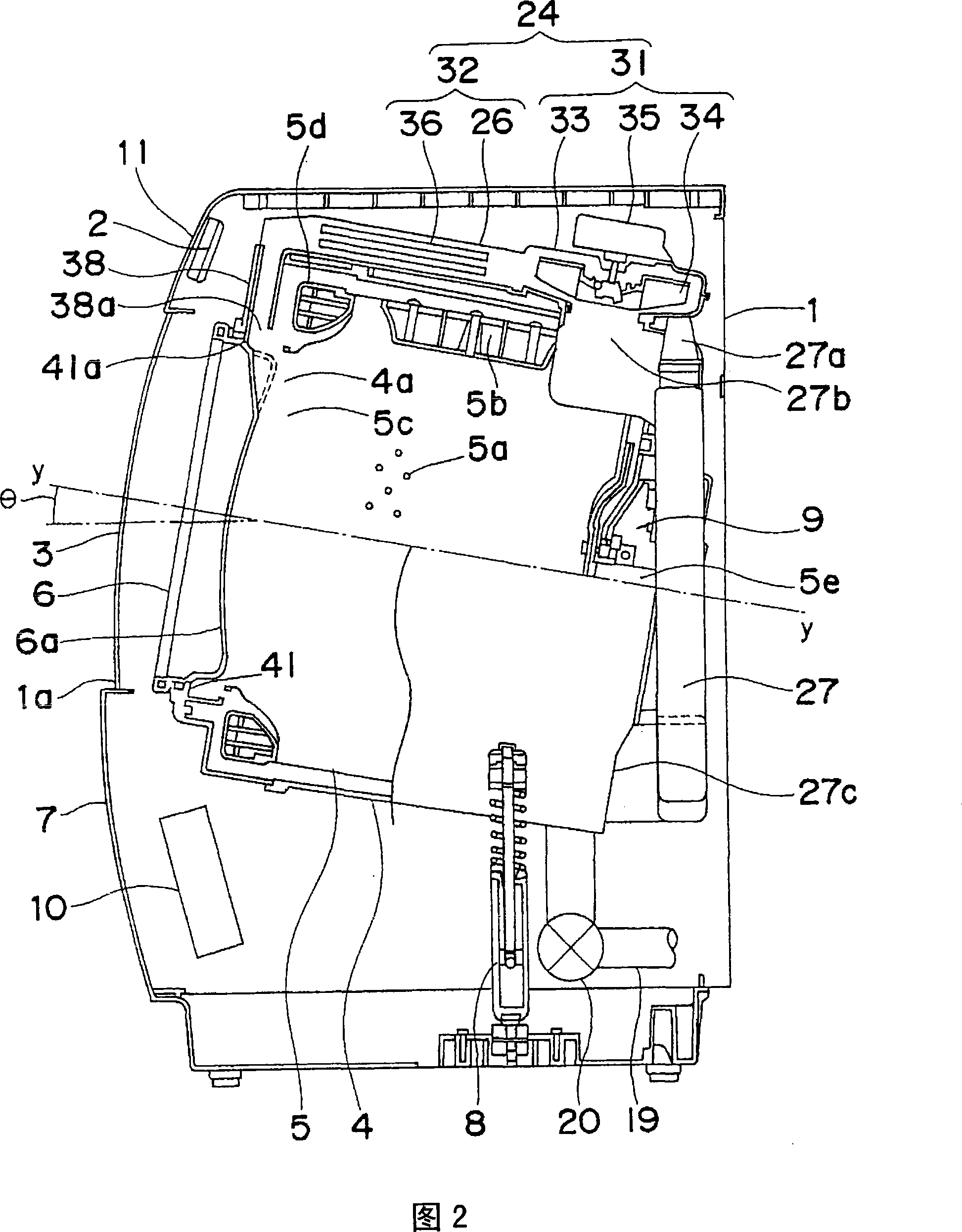
[0191] FIG. 14 shows a schematic cross-sectional view viewed from line F2-F2 in FIG. 13 .

[0192] An outer case opening 111 is formed on the front surface of the outer case 1 . The outer case opening 111 is opened and closed by the door 103 that is rotatable relative to the outer case 1 as described above. In addition, the operation panel 11 having operation keys and a display portion is provided on the front upper portion of the outer case 1 . On the back side of the operation panel 11 (on the side of the water tank 4 ), a control unit 202 for controll...

no. 3 approach

[0269] Fig. 27 is an external perspective view of a drum-type washing and drying machine X according to a third embodiment of the present invention. This drum type washing and drying machine X covers the outer periphery with the outer case 1, and has an outer case opening 111 (refer to FIG. The hinge mechanism is rotatably installed on the outer case 1 . In addition, reference numeral 11 in FIG. 27 is an operation panel.

[0270] FIG. 28 shows a schematic cross-sectional view viewed from line F1 - F1 in FIG. 27 .

[0271] An outer case opening 111 is formed on the front surface of the outer case 1 . The outer case opening 111 is opened and closed by the door 103 that is rotatable relative to the outer case 1 as described above. In addition, the operation panel 11 having operation keys and a display portion is provided on the front upper portion of the outer case 1 . On the back side of the operation panel 11 (on the side of the water tank 4 ), a control unit 2 for controll...


PUM

PropertyMeasurementUnit
Lengthaaaaaaaaaa

Abstract

The invention provides a drum type washing and drying machine, comprising: a water tank (4); a drum (5), which is rotatably arranged in the water tank (4); The air is dehumidified; the heating device is used to heat the air dehumidified by the dehumidification heat exchanger; the blower (131) is used to introduce the air in the drum (5) into the dehumidification heat exchanger, and the air heated by the heating device is Air is blown into the drum (5). Between the drum (5) and the blower (131), a filter (160) is arranged on the upstream side of the air flow generated by the blower (131) during the drying process, that is, on the path on the suction port side. The filter (160) is configured to be immersed in the washing water supplied into the water tank when the washing process or the rinsing process is performed.

Description

technical field [0001] The present invention relates to a drum type washer dryer. Background technique [0002] FIG. 1 shows a schematic sectional view of a conventional drum type washing and drying machine (for example, see Japanese Patent Laid-Open No. 2001-149689). [0003] The drum-type washing and drying machine includes: an outer box 1; a water tank 4 arranged in the outer box 1; a drum 5 arranged in the water tank 4 and containing laundry; a transparent and non-flexible outer door 3; an automatic An automatic door opening and closing mechanism 10 for opening and closing the external door 3; and a drying unit 24 for drying laundry. [0004] An outer case opening 1 a is formed on the front surface of the outer case 1 . Laundry is put in and taken out through the outer case opening 1a. The outer case opening 1 a is opened and closed by an outer door 3 that can slide up and down with respect to the outer case 1 . In addition, an operation panel 11 having operation key...

Claims


Application Information

Patent Timeline
IPC IPC(8): D06F25/00D06F39/10D06F58/02D06F58/22
Inventor 北村进藤田仁志柴崎弘一小森正宪松西信孝三好利成松本正士池上教久
Owner SHARP KK
Why Eureka
Try Eureka