Rail clip of toy galloping car

A flying car and toy technology, applied in the field of toy cars, can solve the problems of affecting the racing effect, flying out of the track, reducing the fun of playing, etc., to achieve the effect of improving the speed of the racing car and the viewing effect, stabilizing the track, and improving the fun

Inactive Publication Date: 2012-05-02
ALPHA GRP CO LTD +1
View PDF0 Cites 0 Cited by
  • Summary
  • Abstract
  • Description
  • Claims
  • Application Information

AI Technical Summary

Problems solved by technology

[0002] Existing toy racing cars for children's games are generally four-wheel drive models. A pair of guide wheels are fixedly installed on both sides of the front part of the toy racing car. The track matching the toy car is semi-closed. The guide wheel walks along the track. Since the guide wheel is only in contact with the track, it is only constrained by the left and right directions and not by the up and down directions. Therefore, when the car is too fast or it is prone to deviating from the track or flying out of the track at the corner, This will cause the car to stop and affect the effect of the car
At the same time, because the toy car runs in the track, the track width is wider and the area is larger. Generally, the track can only be changed in height, and it is difficult to make complex and changeable shapes, and the ornamental value is relatively poor.
Furthermore, due to the erected side panels on both sides of the track, the toy car is blocked, which affects the sight of the observer and reduces the fun of playing.

Method used


Image

  • Rail clip of toy galloping car
  • Rail clip of toy galloping car
  • Rail clip of toy galloping car

Examples


Embodiment 1

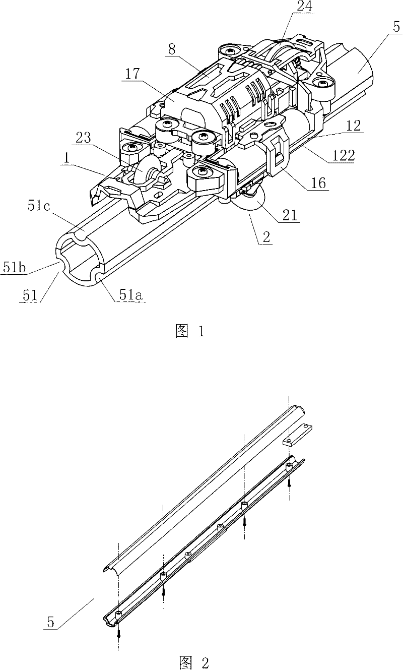
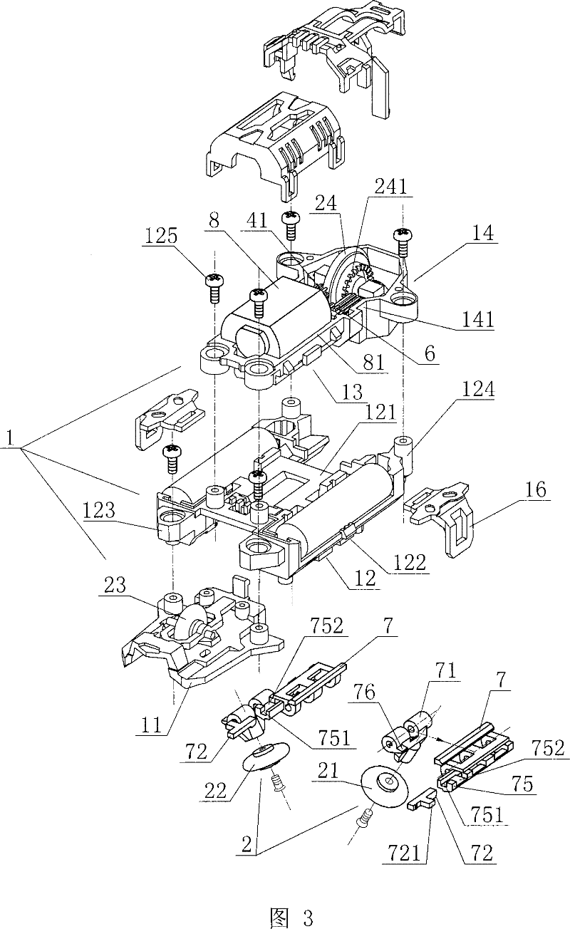
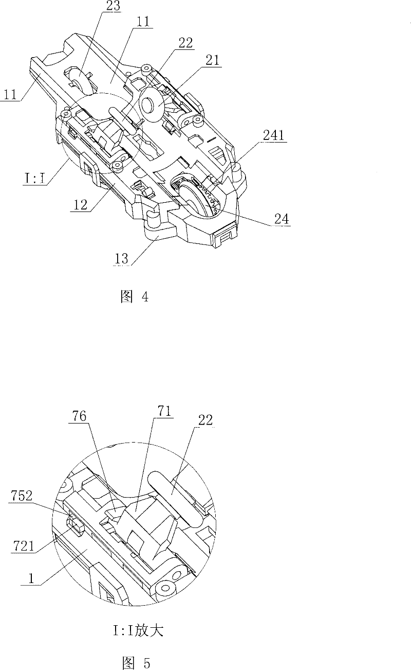
[0028] Embodiment one: if figure 1 , 6 , shown in 10, the grab wheel of the present invention includes the wheel rails that are arranged on both sides of the chassis 1 bottom two sides respectively to grab the wheel rails that are provided with and travel along the wheel rails. Guide wheel comprises the auxiliary guide wheel 23 that is arranged on the middle front of chassis 1 bottom and is arranged on chassis 1 rear and the power wheel 24 that travels along the same track line with auxiliary guide wheel 23. The wheel rails include two groove rails 51a, 51b symmetrically arranged on both sides of the track 5 for the left and right rows of locking wheels to lock and run and a groove rail 51c arranged in the middle of the upper part of the track 5 for the guide wheels to run. The clamping wheels 21, 22 of the toy rail car of this example are locked in the groove rails 51a, 51b of the track 5 and travel along the groove rails 51a, 51b, and the power guide wheel 24 and the auxili...

Embodiment 2

[0029] Embodiment two: if Figure 11 , 12 As shown, the holding wheel of the present invention includes two holding wheels 21 and 22 symmetrically arranged on both sides of the bottom of the chassis 1 respectively holding the wheel rails provided on both sides of the toy car track 5 and traveling along the wheel rails. The guide wheels include an auxiliary guide wheel 29a and a power wheel 29b which are respectively arranged at the front and rear ends of the bottom of the chassis 1 and can run on the surface of the track 5. The rim surfaces of the auxiliary guide wheel 29a and the power wheel 29b are arranged as grooves matching the track surface . The wheel rails include two groove rails 51a, 51b symmetrically arranged on both sides of the track 5 for the left and right rows of locking wheels to hold and drive. The locking wheels 21, 22 provided on both sides of the lower part of the toy rail car in this example are locked in the groove rails 51a, 51b of the track 5 and run...

Embodiment 3

[0030] Embodiment three: as Figure 13 , 14 As shown, the holding wheel of the present invention includes two holding wheels 21, 22 symmetrically arranged on both sides behind the bottom of the chassis 1, respectively holding the wheel rails provided on both sides of the toy car track 5 and traveling along the wheel rails. The guide wheels include the auxiliary guide wheels 25, 26 which are arranged on the front sides of the bottom of the chassis 1 and are respectively in line with the rear locking wheels and run on the same track line. The rim surfaces of the locking wheels 21, 22 and the auxiliary guide wheels 25, 26 are arranged as grooves matching the track surfaces. The holding wheels 21, 22 and auxiliary guide wheels 25, 26 hold the wheel rails through grooves and travel on the wheel rails. The wheel rails include two groove rails 51a, 51b symmetrically arranged on both sides of the track 5 for the left and right rows of locking wheels to hold and drive. In this examp...


PUM


Abstract

The invention relates to a trapped track mechanism of a toy run away, which comprises a chassis and at least a pair of symmetrical enclasped wheels that are arranged at the bottom of the chassis of the toy run away, which can enclasp a track of the toy run away and drive along the track. The invention effectively ensures that the toy run away is closely combined with the track and drives at a high speed without digression. A wheel frame is rotatablely arranged on the chassis and a locking pin of the wheel frame can cause two guide wheels to unwrap a proper angle, thus being convenient for thetoy run away to enclasp the track and also preventing the guide wheels from deviating from the track. During racing processing, the trapped track mechanism of the invention can effectively ensure that the toy run away can stably enclasp the track and drive at a high speed without digression, thus, realizing the existing toy run away drives by enclasping the track in stead of drives in the track, the toy run away can completely expose outside the track, thus promoting racing speed and appreciation effect; a strip track is adopted, which not only reduces the volume of the track but also can be made into various forms so as to realize various style shuttling of the toy run away and promote the interest of playing.

Description

technical field [0001] The invention relates to the field of toy cars, in particular to a rail clamping mechanism for a toy car. Background technique [0002] Existing toy racing cars for children's games are generally four-wheel drive models. A pair of guide wheels are fixedly installed on both sides of the front part of the toy racing car. The track matching the toy car is semi-closed. The guide wheel walks along the track. Since the guide wheel is only in contact with the track, it is only constrained by the left and right directions and not by the up and down directions. Therefore, when the car is too fast or it is prone to deviating from the track or flying out of the track at the corner, This will cause the car to stop and affect the effect of the car. Simultaneously because toy car travels in track, makes track width wider, area is bigger, and track generally can only change height, and is difficult to make complex and changeable molding, and appreciation is relative...

Claims


Application Information

Patent Timeline
Patent Type & Authority Patents(China)
IPC IPC(8): A63H21/04
CPCA63H17/14A63H18/028A63H21/04
Inventor 蔡东青
Owner ALPHA GRP CO LTD
Why Eureka
Try Eureka