
Toy runaway device

A technology for flying cars and toys, applied in the field of toy cars, can solve the problems of affecting the effect of racing cars, affecting the sight of the observer, flying out of the track, etc., so as to improve the speed of the racing car and the viewing effect, improve the fun and appreciation, and reduce the volume and air. The effect of resistance

Inactive Publication Date: 2008-09-17
ALPHA GRP CO LTD +1
View PDF0 Cites 1 Cited by
  • Summary
  • Abstract
  • Description
  • Claims
  • Application Information

AI Technical Summary

Problems solved by technology

[0002] Existing toy racing cars for children's games are generally four-wheel drive models. A pair of guide wheels are fixedly installed on the front of the toy racing car. The wheel walks along the track. Since the guide wheel is only in contact with the track, it is only constrained by the left and right directions and not by the up and down directions. Therefore, the speed of the car is too fast or it is easy to detach from the track or fly out of the track at the corner. It will cause the car to stop and affect the effect of the car
At the same time, because the toy car runs in the track, the track width is wider and the area is larger. Generally, the track can only be changed in height, and it is difficult to make complex and changeable shapes, and the ornamental value is relatively poor.
Furthermore, due to the erected side panels on both sides of the track, the toy car is blocked, which affects the sight of the observer and reduces the fun of playing.

Method used


Image

  • Toy runaway device
  • Toy runaway device
  • Toy runaway device

Examples


Embodiment 1

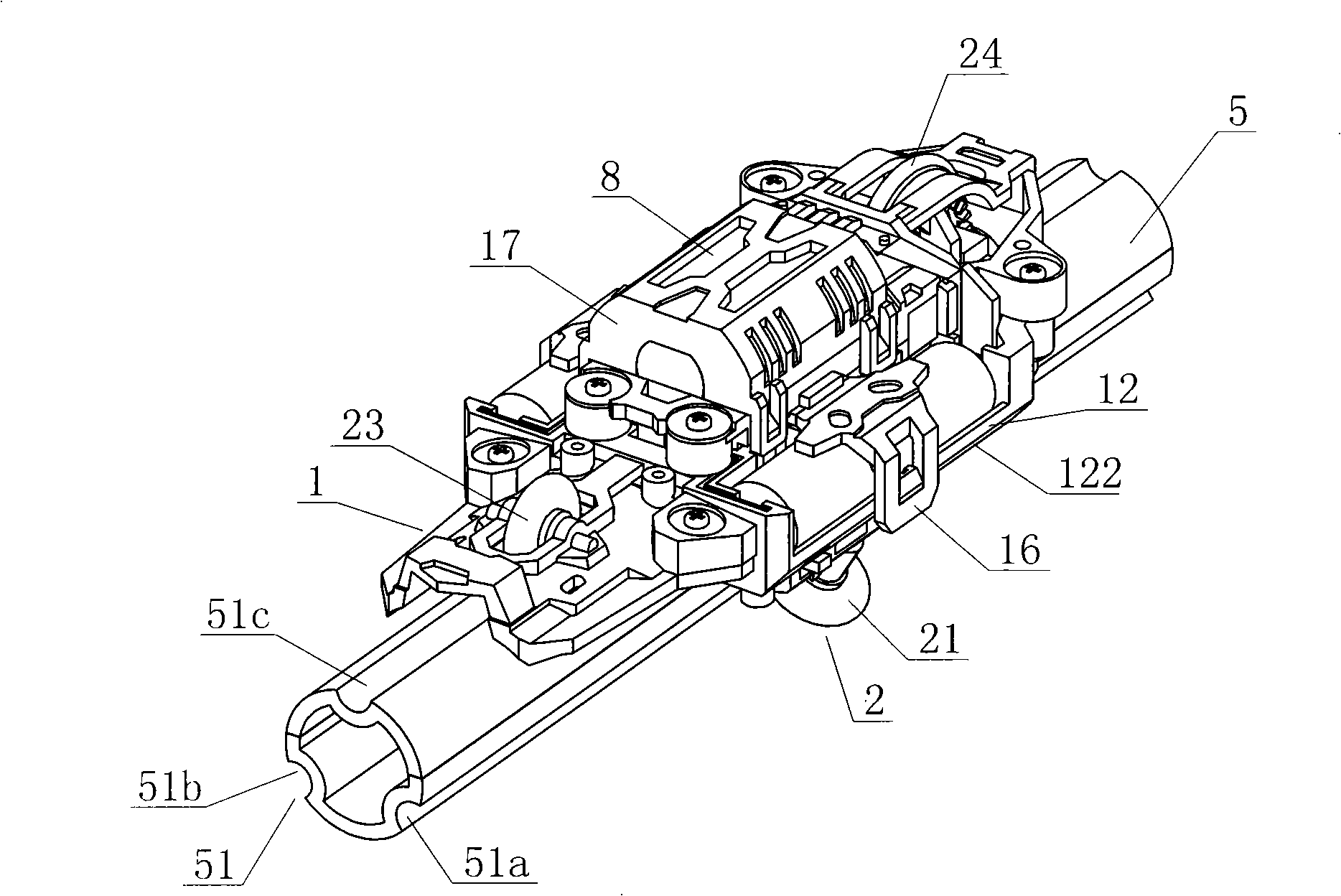
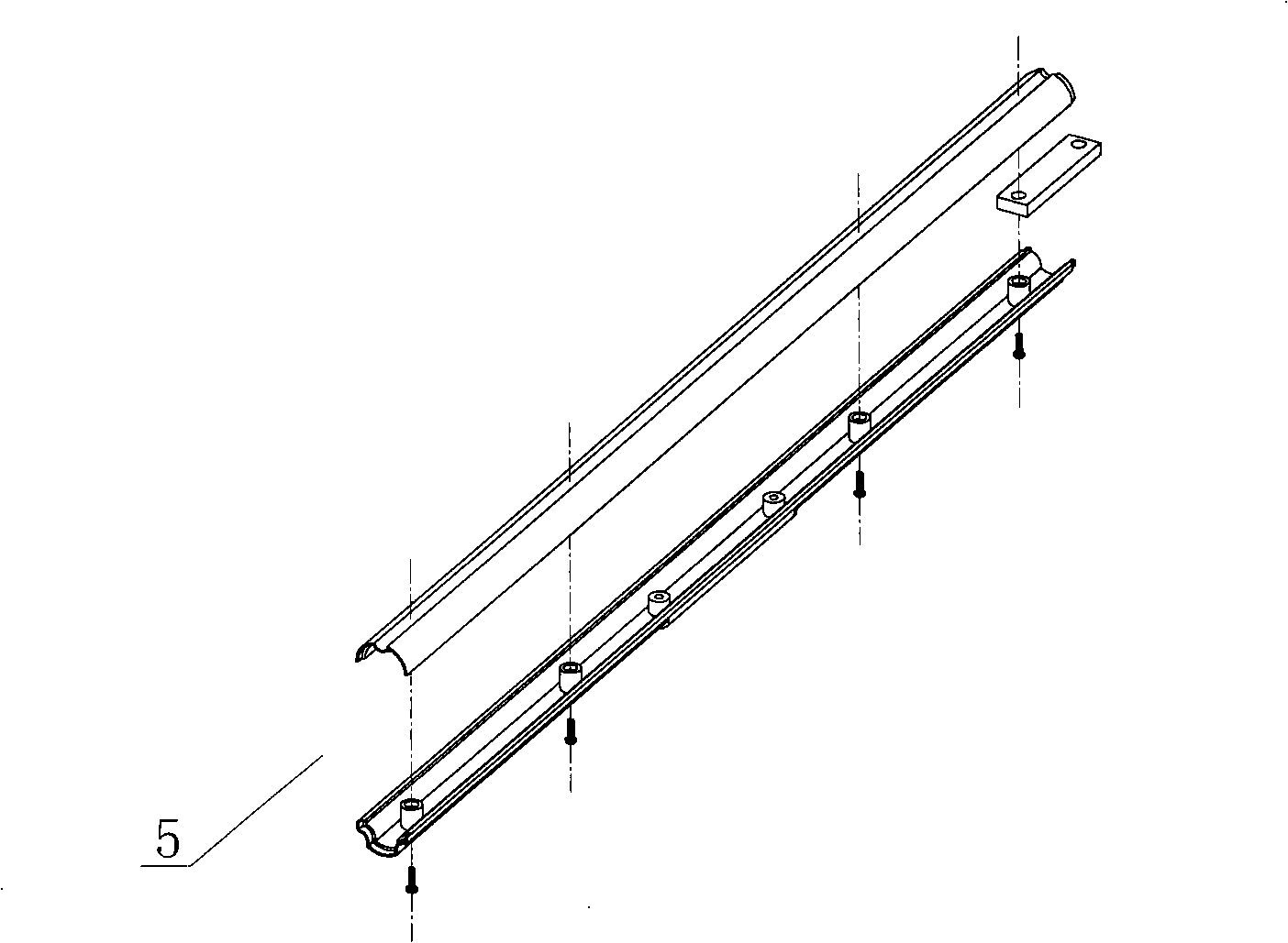
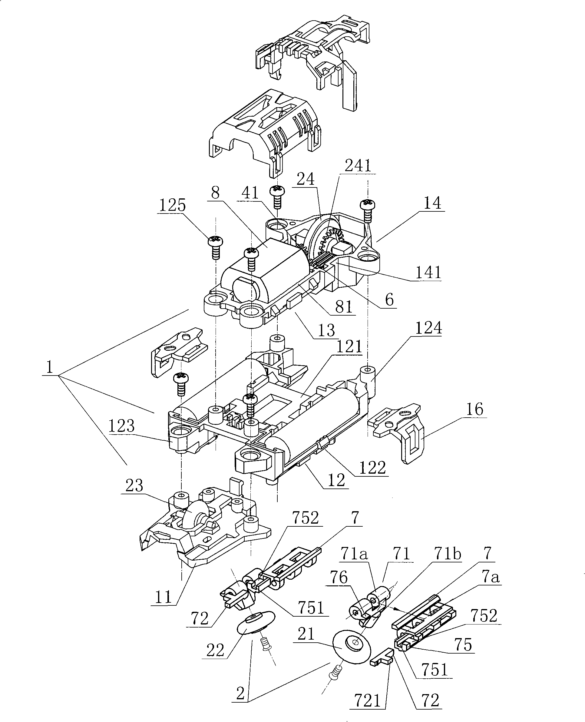
[0043] Embodiment one: if figure 1 , 6 As shown in , 10, the locking wheel of the present invention includes two wheel rails that are symmetrically arranged on both sides of the bottom of the chassis 1 to respectively hold the wheel rails provided on both sides of the toy speed track 5 and run along the wheel rails 21, 22, The guide wheels include an auxiliary guide wheel 23 arranged in the middle of the front part of the bottom of the chassis 1 and a power wheel 24 arranged at the rear of the chassis 1 and traveling along the same track with the auxiliary guide wheel 23 . The wheel rails include two groove rails 512a, 512b symmetrically arranged on both sides of the track 5 for the left and right rows of locking wheels to hold and run. The clamping wheels 21, 22 of the toy rail car of this example are locked in the groove rails 51a, 51b of the track 5 and travel along the groove rails 51a, 51b, and the power guide wheel 24 and the auxiliary guide wheel 23 travel along the gr...

Embodiment 2

[0044] Embodiment two: if Figure 11 , 12 As shown, the holding wheel of the present invention includes two holding wheels 21 and 22 symmetrically arranged on both sides of the bottom of the chassis 1 respectively holding the wheel rails provided on both sides of the toy car track 5 and traveling along the wheel rails. The guide wheels include an auxiliary guide wheel 29a and a power wheel 29b which are respectively arranged on the front and rear parts of the bottom of the chassis 1 and can run on the track 5 surface. The wheel rail includes two groove rails 512a, 512b symmetrically arranged on both sides of the track 5 for the left and right rows of locking wheels to hold and drive. The locking wheels 21, 22 provided on both sides of the lower part of the toy rail car in this example are locked in the groove rails 51a, 51b of the track 5 and run along the groove rails 51a, 51b. The auxiliary guide wheel 29a and the power guide wheel 29b pass through the The groove that edge...

Embodiment 3

[0045] Embodiment three: as Figure 13 , 14 As shown, the holding wheel of the present invention includes two holding wheels 21, 22 symmetrically arranged on both sides behind the bottom of the chassis 1, respectively holding the wheel rails provided on both sides of the toy car track 5 and traveling along the wheel rails. The guide wheels include the auxiliary guide wheels 25, 26 which are arranged on the front sides of the bottom of the chassis 1 and are respectively in line with the rear locking wheels and run on the same track line. The rim surfaces of the locking wheels 21, 22 and the auxiliary guide wheels 25, 26 are configured as concave surfaces 21a, 22a, 25a, 26a that match the track surfaces. The holding wheels 21, 22 and auxiliary guide wheels 25, 26 hold the wheel rails through grooves and travel on the wheel rails. The wheel rail includes two groove rails 512a, 512b symmetrically arranged on both sides of the track 5 for the left and right rows of locking wheels...


PUM


Abstract

The invention relates to a toy flying car device, comprising a car body and a bar-shaped rail, wherein the car body is composed of a chassis, a car cover, a plurality of wheels, a driving motor and a transmission apparatus; a battery chamber and a motor chamber are arranged on the chassis; the wheels are composed of at least one guide wheel and a pair of enclasp wheel capable of clamping the rail and moving along the rail; at least one of the guide wheel and the enclasp wheels is arranged as the driving wheel; a support capable of three-dimentional deformation is arranged beneath the rail; the battery chambers are arranged at two sides of the motor chamber in the middle of the chassis to balance the toy car weight for the balance of the car body; a concave matched with the shape of the rail and capable of holding the rail is arranged at the bottom of the chassis. The flying toy car has the advantages that the car can be fast held to the rail without derailment when running along the rail at a high speed, which enhances the enjoyment and watchfulness; the chassis is composed of a plurality of separated sections crossingly connected with each other which provides convenience for the upgrading of the flying toy car and enhances the playfulness; the toy car is closely held to the rail due to the adoption of the concave at the bottom of the chassis, therefore, the air resistance is reduced.

Description

technical field [0001] The invention relates to the field of toy cars, in particular to a toy flying car device traveling on rails. Background technique [0002] Existing toy racing cars for children's games are generally four-wheel drive models. A pair of guide wheels are also fixedly installed on the front of the toy racing car. The wheel walks along the track. Since the guide wheel is only in contact with the track, it is only constrained by the left and right directions and not by the up and down directions. Therefore, the speed of the car is too fast or it is easy to get off the track or fly out of the track at the corner. It will cause the suspension of the car and affect the effect of the car. Simultaneously because toy car travels in track, makes track width wider, area is bigger, and track generally can only change height, and is difficult to make complex and changeable molding, and appreciation is relatively poor. Furthermore, due to the erected side panels on bo...

Claims


Application Information

Patent Timeline
Patent Type & Authority Applications(China)
IPC IPC(8): A63H21/04
Inventor 蔡东青
Owner ALPHA GRP CO LTD
Learn More