Airtight positive pressure operation platform

A work machine, work machine technology, applied in the direction of removing smoke and dust, cleaning methods and utensils, chemical instruments and methods, etc., can solve problems such as injuries, and achieve the effect of effective control and avoidance of adverse effects

Inactive Publication Date: 2008-07-30
AU OPTRONICS CORP
View PDF0 Cites 0 Cited by
  • Summary
  • Abstract
  • Description
  • Claims
  • Application Information

AI Technical Summary

Problems solved by technology

Furthermore, the above-mentioned organic substances will cause harm to the human body of the engineers and operators working in the operation area 30, so the control of the escape of organic substances is becoming increasingly important.

Method used


Image

  • Airtight positive pressure operation platform
  • Airtight positive pressure operation platform
  • Airtight positive pressure operation platform

Examples


Embodiment Construction

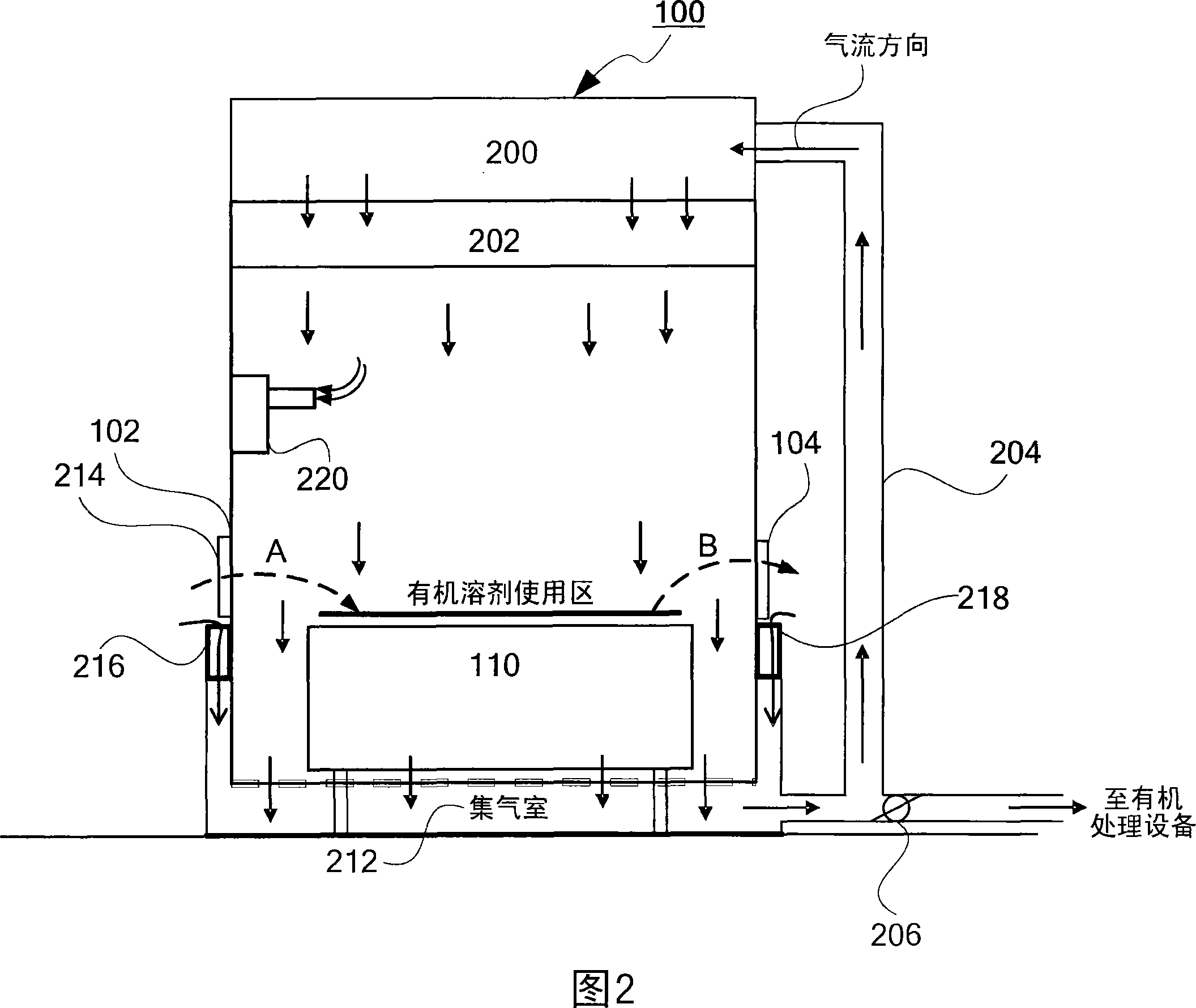
[0025] Fig. 2 is a schematic diagram of the first embodiment of the airtight positive pressure operating machine platform of the present invention. As shown in FIG. 2 , the airtight positive pressure operating machine 100 of the present invention includes an air supply chamber 200 , a fan-filter unit 202 (FFU), a workpiece transmission port 102 and a return air pipe 204 . The air supply chamber 200 is used for accommodating circulating air supplied to the inside of the airtight positive pressure working machine 100 . The fan-filter unit 202 has a fan and a filter (for example: HEPA, ULPA or components with similar functions) that drive the gas to generate flow, and are used to drive the circulating airflow of the air supply chamber 200 to be delivered to the inside of the airtight positive pressure operating machine 100 , that is, the organic solvent use area where the working platform 110 is located. The first air hood device 216 is arranged beside the workpiece conveying 10...


PUM


Abstract

The invention relates to a closed positive-pressure operation machine station with a workpiece conveying port. The closed positive-pressure operation machine station has an air supply chamber, a fan-filter screen unit, a first air mask device and an air return pipe. The air supply chamber holds cycle air provided for the closed positive-pressure operation machine station. The fan-filter screen unit delivers the cycle air in the air supply chamber to internal of the closed positive-pressure operation machine station. The first air mask device is positioned beside the workpiece conveying port to control the cycle air to be dissipated from the workpiece conveying port. The air return pipe can send the cycle air inside the positive-pressure operation machine station back to the air supply chamber. The closed positive-pressure operation machine station of the invention can not only reduce the air required to be supplied from outside of the self-closing positive-pressure operation machine station outside, but also avoid the dissipation of organic matter from the workpiece conveying port.

Description

technical field [0001] The invention relates to an operating machine for manufacturing substrates, in particular to an airtight positive pressure operating machine capable of reducing gas supply at a facility and saving energy. Background technique [0002] FIG. 1 is a schematic diagram of an existing operating machine. The work machine 10 is, for example, a photoresist coater, and is installed on the raised floor of the clean room. The clean room is a design environment for the overall air return. In order to maintain the cleanliness of the clean room, the clean air is supplied from above, and the air inside the operating machine 10 will be brought to the bottom of the raised floor, and then returned to the The top of the work area 30 where the work machine is located. For a general work machine 10 , the workpiece (eg substrate) is delivered to the work platform 110 inside the work machine 10 through the work conveying port 102 (shown as the work conveying path A) of the ...

Claims


Application Information

Patent Timeline
IPC IPC(8): B08B15/00
Inventor 谢彩惠林立伟
Owner AU OPTRONICS CORP
Why Eureka
Try Eureka