Pull rod lock mode hydraulic tyre vulcanizer

A tire vulcanization and tie-rod locking technology, which is applied to tires, other household appliances, household appliances, etc., can solve the problems of increasing the maintenance difficulty and maintenance cost of the pressurized oil cylinder, and reducing the accuracy of the quasi-accuracy, achieving a simple structure, avoiding oil leakage and Effects of contamination, ease of maintenance or repair

Active Publication Date: 2008-07-30
SINO ARP TIRES EQUIP TECH (SUZHOU) CO LTD
View PDF1 Cites 31 Cited by
  • Summary
  • Abstract
  • Description
  • Claims
  • Application Information

AI Technical Summary

Problems solved by technology

However, in order to realize the upward pressure of the lower mold, the lower mold in the lower structure of the pressurized cylinder cannot be directly fixed with the support structure, but is floating. Due to the existence of the gap, it is inevitable that the alignment during mold closing Decrease in accuracy; Secondly, the location of the pressurized cylinder greatly increases the maintenance difficulty and cost of the pressurized cylinder

Method used


Image

  • Pull rod lock mode hydraulic tyre vulcanizer
  • Pull rod lock mode hydraulic tyre vulcanizer
  • Pull rod lock mode hydraulic tyre vulcanizer

Examples


Embodiment 1

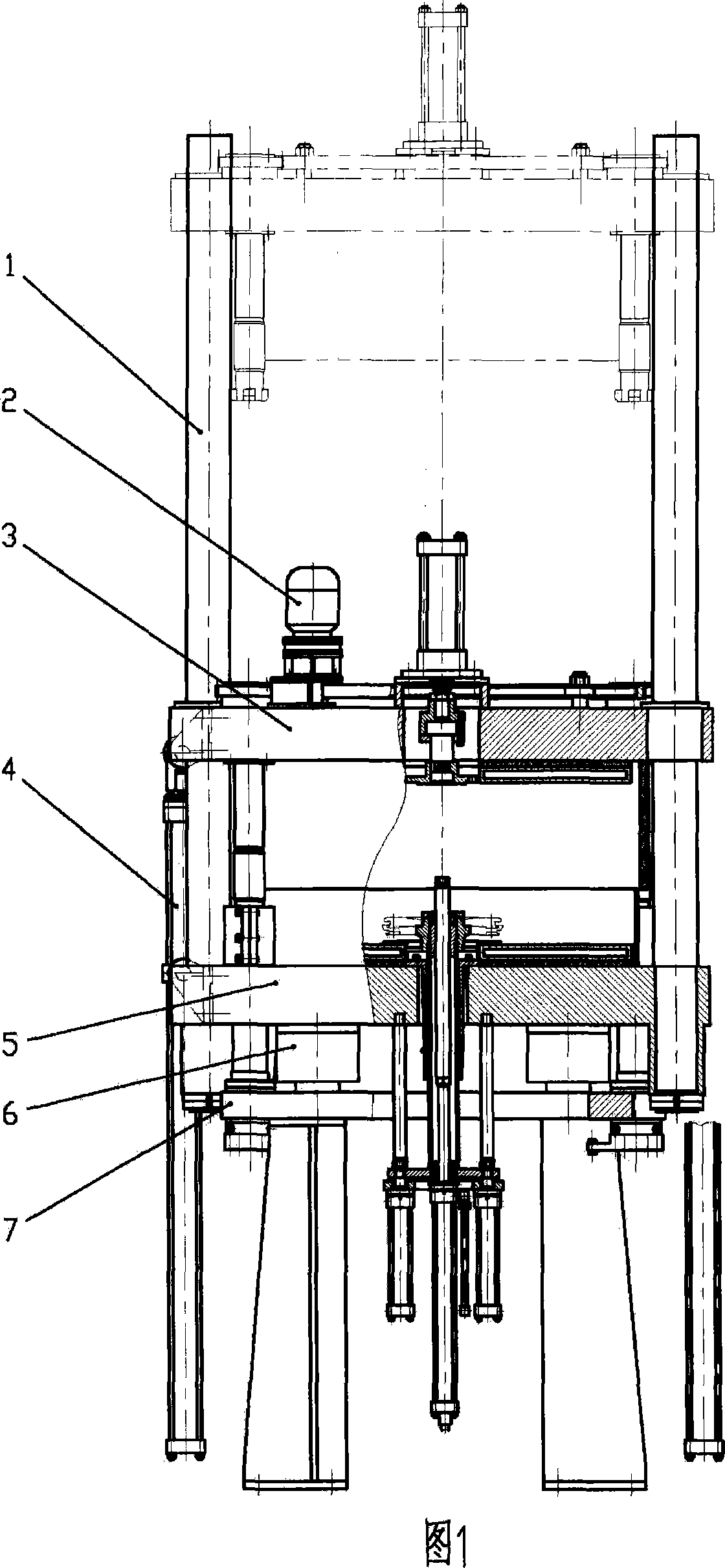
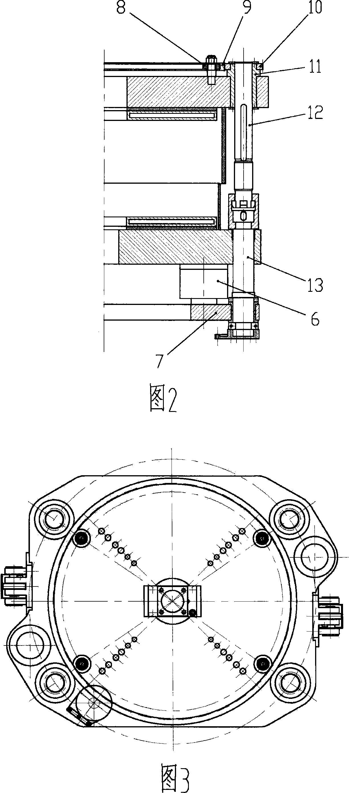
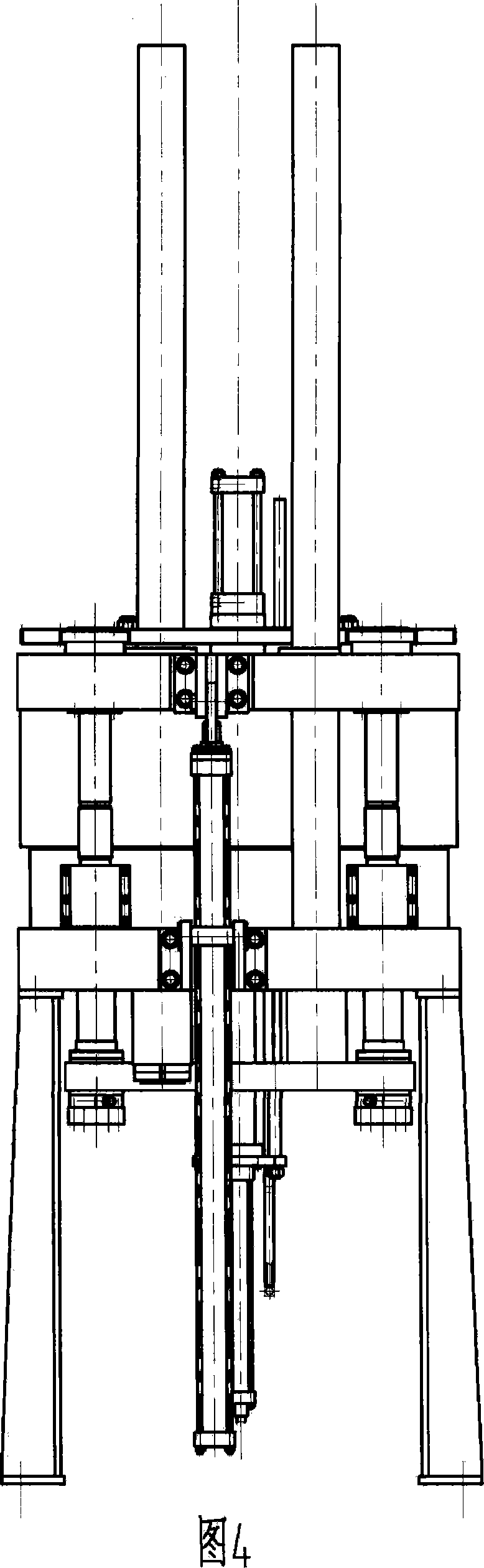
[0043] Referring to Fig. 1 to Fig. 4, a hydraulic tire vulcanizing machine with pull rod lock mode is a hydraulic tire vulcanizing machine with a double-column single-mode structure, which includes a column 1, a mold-adjusting gear motor 2, an upper beam 3, and an opening and closing mold. Oil cylinder 4, lower beam 5, pressurized oil cylinder 6, pressurized pallet 7, support wheel 8, mold adjusting ring gear 9, mold adjusting pinion 10, mold adjusting nut 11, upper pull rod 12, lower rod 13, upper heating plate , Lower hot plate, central mechanism, upper mold, lower mold.

[0044] Among them, there are two uprights 1 for guiding mold opening and closing, which are respectively fixed on the lower crossbeam and are located on the left and right sides of the vulcanizing machine respectively. When molding, an additional bending moment is generated; the left and right sides of the upper beam 3 are respectively equipped with guide sleeves or linear bearings, which slide or roll wit...

Embodiment 2

[0049] Referring to Fig. 5, a hydraulic tire vulcanizing machine with a tie rod lock mode is a hydraulic tire vulcanizing machine with a double-column single-mode structure. Instead of the four tie rods in Embodiment 1, this is mainly to change the number of mold clamping tie rods according to the magnitude of the clamping force, so as to be suitable for tire vulcanization with different requirements.

Embodiment 3

[0051] Referring to Fig. 6, a hydraulic tire vulcanizing machine in pull bar lock mode is a hydraulic tire vulcanizing machine with four-column single-mode structure. The difference from Embodiment 1 is that it is replaced by four columns at the four corners of the vulcanizing machine. The two uprights in Embodiment 1 are replaced by six tie rods at the six corners of the vulcanizing machine. The four tie rods in Embodiment 1 are mainly changed according to the clamping force and the size of the tire mold to change the number of uprights and clamping rods, so that Suitable for tire vulcanization with different requirements.


PUM


Abstract

The invention discloses a hydraulic tire curing press with a pull rod locking module. The invention consists of a frame consisting of a lower beam and a supporting part, an upper beam, an upper and lower thermal plate, an opening and closing die cylinder, a central structure and a pressurized structure. The upper beam is driven by the opening and closing die cylinder and has freedom of moving from the top to the bottom. An upper die and a lower die are directly arranged between the upper thermal plate and the lower thermal plate and are respectively fixed connected with the upper beam and the lower beam. The pressurized structure consists of a pulling rod, a pressurized splint and a pressurized cylinder. The pulling rod is evenly arranged corresponding to the axle wire of in the tire module. The upper terminal of each pulling rod is fixedly connected with the upper beam and the lower terminal of each pulling rod is fixedly connected with the pressurized plate traveling through the lower beam; the pressurized cylinder is fixed on the bottom of the lower beam and the piston terminal of the cylinder is fixedly connected with the pressurized plate; the pulling rod is arranged with a locking die structure and an adjusting die structure. The invention increases the working precision and reducing the manufacturing cost, at the same time, the invention also has the advantages of avoiding the problem of oil leaking and contamination, being convenient for the cylinder maintenance, simplifying the forcing chain of the locking die force and reducing the manufacturing cost of the curing press.

Description

technical field [0001] The invention relates to a tire vulcanizing equipment, in particular to a hydraulic tire vulcanizing machine in a pull bar lock mode. Background technique [0002] The vulcanization of automobile tires has been popularized and applied since the 1950s, and the mechanical vulcanizer is generally used at first. The high requirements also put forward higher and higher requirements for the working precision of the vulcanizing machine. Therefore, the hydraulic vulcanizing press with higher working precision has gradually replaced the traditional mechanical vulcanizing press. [0003] Existing hydraulic tire vulcanizing machines include two types of frame structure and column structure, the difference mainly lies in that the main support structure adopts a fixed beam type frame or a column. Taking the hydraulic tire vulcanizing machine with frame structure as an example, a common structure includes frame body, upper beam, mold openin...

Claims


Application Information

Patent Timeline
Patent Type & Authority Applications(China)
IPC IPC(8): B29C35/02B29C33/20B29L30/00
Inventor 张正罗姚剑芳
Owner SINO ARP TIRES EQUIP TECH (SUZHOU) CO LTD
Why Eureka
Try Eureka