
Vacuum cavity positioning structure

A technology for positioning structures and vacuum chambers, applied in lamination devices, lamination auxiliary operations, lamination, etc., can solve problems such as loss of drive devices, reduction of cavity sealing effect, and shortened service life

Inactive Publication Date: 2008-07-30
C SUN MFG
View PDF2 Cites 0 Cited by
  • Summary
  • Abstract
  • Description
  • Claims
  • Application Information

AI Technical Summary

Problems solved by technology

[0005] However, although this method can ensure the close contact between the substrate and the membrane body, when the air is pressurized, the air is blocked by the membrane body and produces a reverse force, and the force occurs instantaneously and it is difficult to predict the magnitude of the force. The driving device that pushes against the lower plate is overloaded, so that the sealing between the upper and lower plates cannot be guaranteed, and the sealing effect of the cavity is greatly reduced. To achieve the expected high vacuum state

Method used


Image

  • Vacuum cavity positioning structure
  • Vacuum cavity positioning structure
  • Vacuum cavity positioning structure

Examples


Embodiment Construction

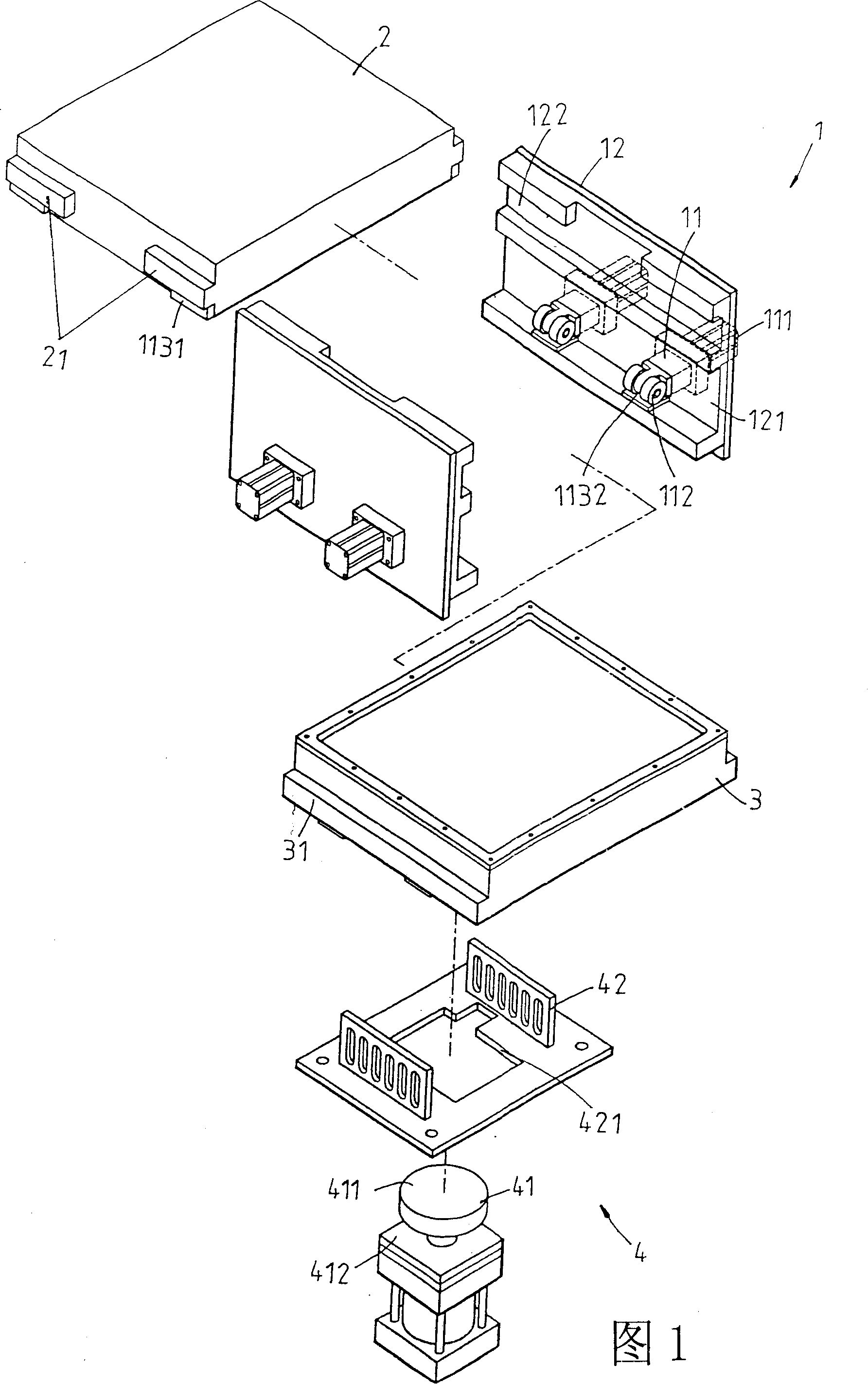
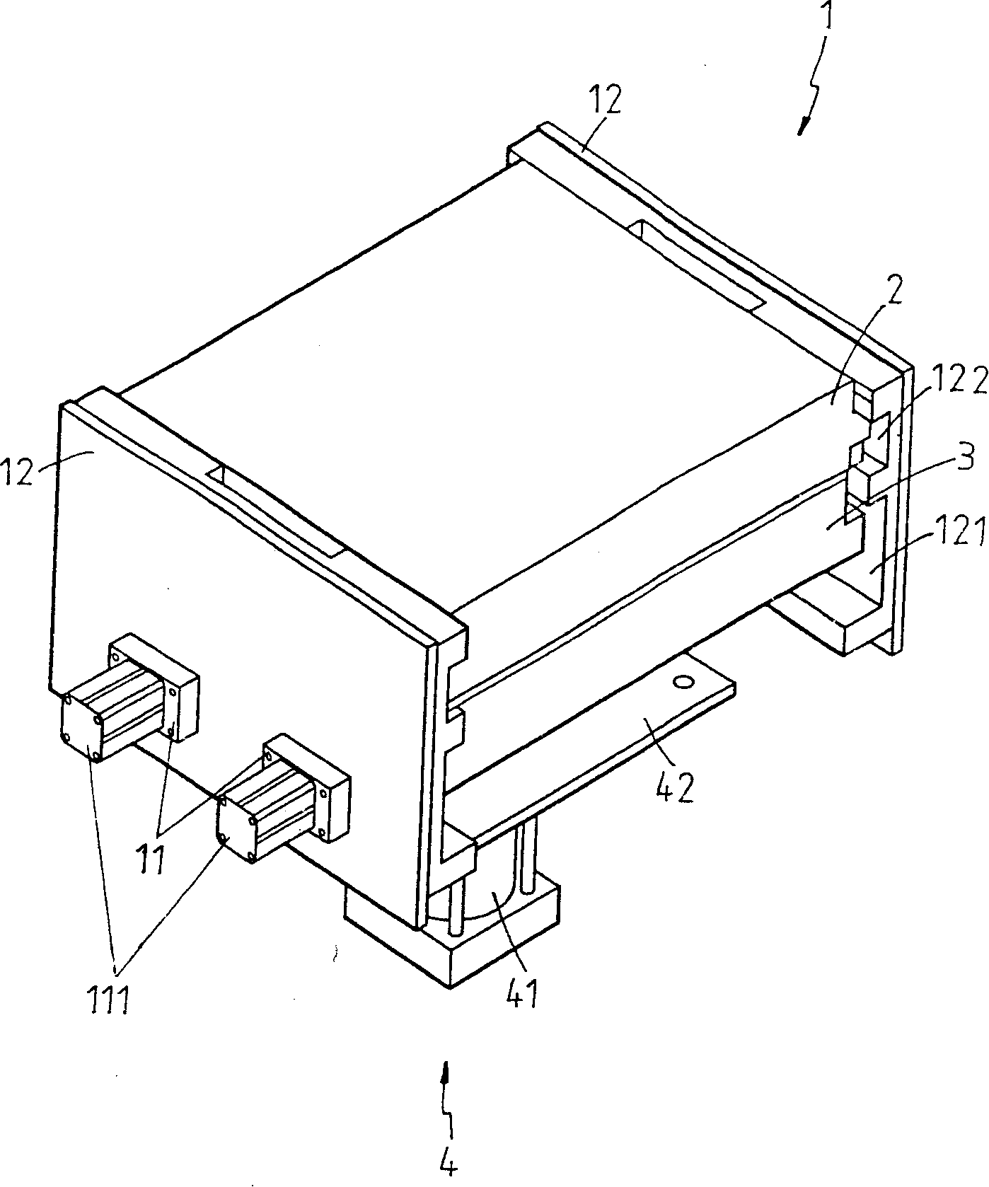
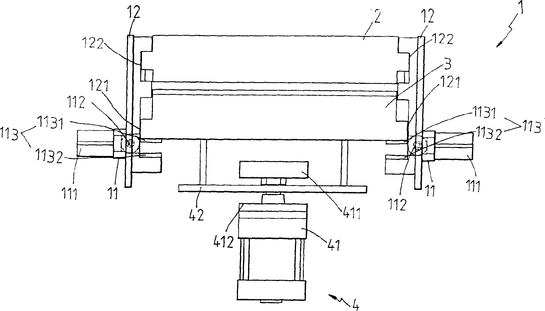
[0039] The present invention is a vacuum cavity positioning structure, please refer to Figure 1 and figure 2 As shown in the schematic diagram of disassembly and assembly, the cavity mainly includes a positioning structure 1, a lifting structure 4, an upper plate 2, and a lower plate 3, wherein:

[0040] The positioning structure 1 includes corresponding two side plates 12, and the two side plates 12 are respectively recessed with corresponding two long grooves 121, and the two side plates 12 are also respectively recessed with corresponding two short grooves 122. The two short grooves 122 are located above the two long grooves 121, the corresponding two short grooves 122 are used to accommodate the upper plate 2, the corresponding two long grooves 121 are used to accommodate the lower plate 3, and the single The bottom of the long groove 121 of the side plate 12 is provided with two positioning groups 11, and the bottom of the long groove 121 of the corresponding side plate 1...


PUM


Abstract

The invention relates to a structure for locating a vacuum cavity. The cavity mainly comprises a location structure, a lifting structure, an upper board and a lower board, wherein, the location structure is used for arranging and setting as well as locating the upper board; the location structure is provided with a long groove which is used for arranging and setting the lower board; at least a group of scalable locating groups is arranged on the bottom of the long groove in the location structure; a wheel body which can insert into or remove from the long groove is arranged on the front end of the locating group; the lifting structure is used for pushing the lower board to move along the long groove; the locating efficiency of the lower board can be enhanced by adopting the wheel body of the locating group to insert into the long groove and force to lift the lower board. The invention has the advantages of prolonging the service life, easy disassembly and convenient repairing.

Description

technical field [0001] The invention relates to a vacuum cavity positioning structure. Background technique [0002] In the high-tech electronics industry, circuit board printing technology is a very important part. In the manufacture of printed circuit boards, there are several ways to press and form materials to be laminated. The existing technical means is to use vacuum lamination equipment, which can be used relatively close Or separate the upper and lower plates, and put the film body and the substrate between the upper and lower plates. The upper and lower plates are pushed by the power of the cylinder, and the volume space of the upper and lower plates is evacuated into a vacuum state. The upper and lower plates are pressurized so that the film body is tightly attached to the substrate. As disclosed in the Japanese Patent Publication No. 2005-035239 "Vacuum Lamination Equipment and Method", the vacuum lamination equipment uses two auxiliary drive devices The support ...

Claims


Application Information

Patent Timeline
Patent Type & Authority Applications(China)
IPC IPC(8): B32B38/00B32B37/10
Inventor 刘光强赖金森李燕昌
Owner C SUN MFG
Learn More