Control device for automatic transmission

一种自动变速器、控制装置的技术,应用在传动装置、发动机控制、流体传动装置等方向,能够解决驾驶性能恶化、锁止离合器发热量大、加速困难等问题,达到提高驾驶性能的效果

Inactive Publication Date: 2008-07-30
HONDA MOTOR CO LTD
View PDF2 Cites 18 Cited by
  • Summary
  • Abstract
  • Description
  • Claims
  • Application Information

AI Technical Summary

Problems solved by technology

[0010] When driving on an uphill road, the driving resistance increases, and it is difficult to accelerate compared with a flat road
Therefore, when running uphill at the target slip rate on a flat road as in the past, the stabilized lockup clutch may generate too much heat and deteriorate durability, so the lockup clutch is disengaged to deal with it. As a result, there is a problem that the fuel consumption on the uphill road deteriorates and drivability deteriorates.

Method used


Image

  • Control device for automatic transmission
  • Control device for automatic transmission
  • Control device for automatic transmission

Examples


Embodiment Construction

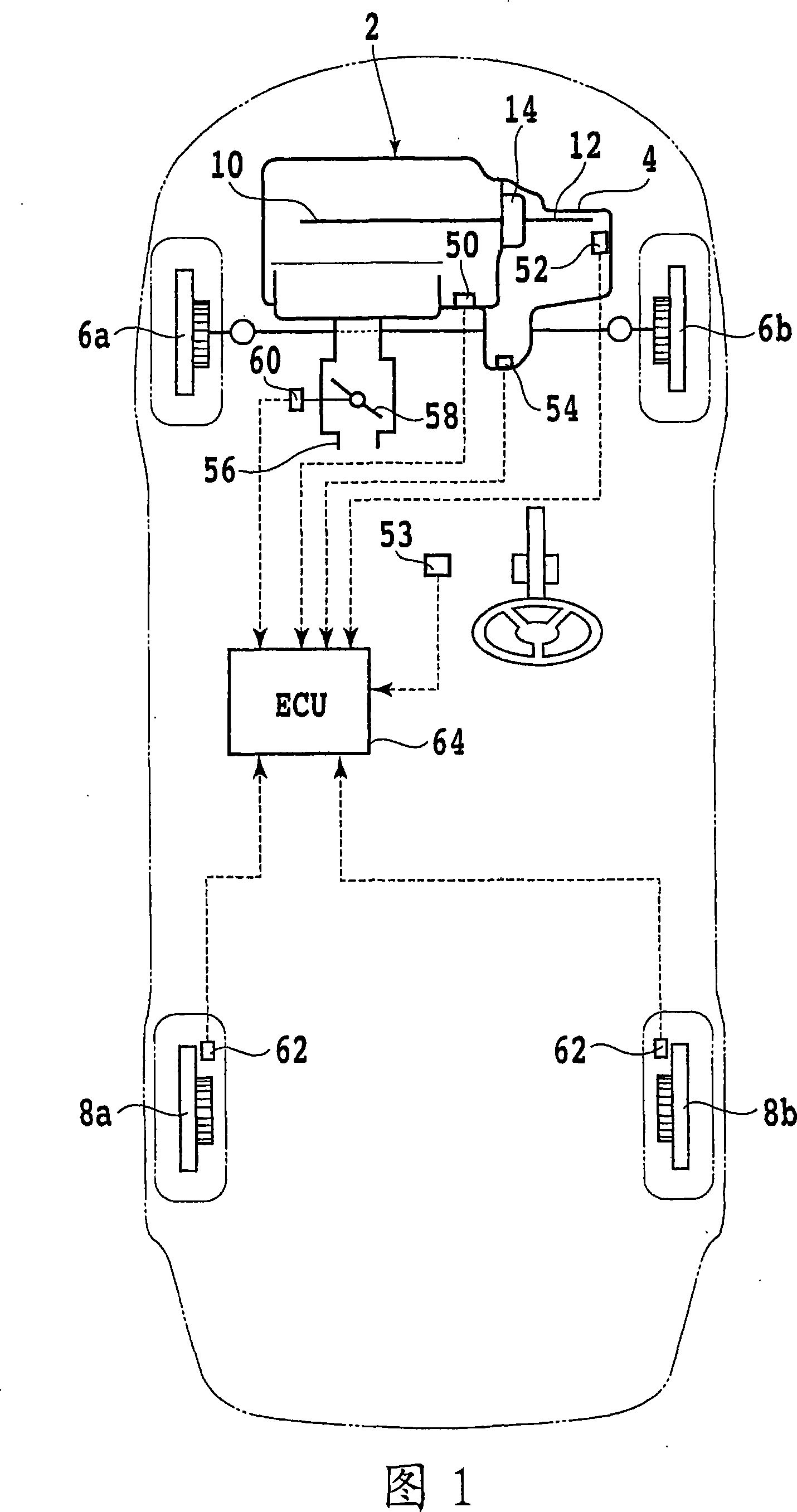
[0041] Fig. 1 is an overall configuration diagram of a vehicle equipped with a control device of the present invention. This vehicle is a front-wheel drive vehicle and has: a pair of left and right drive wheels 6a, 6b, the torque of the engine 2 is transmitted to the drive wheels 6a, 6b via an automatic transmission 4; and a pair of left and right driven wheels 8a that rotate with driving , 8b. A known torque converter 14 is interposed between the crankshaft 10 of the engine 2 and the main shaft 12 of the automatic transmission 4.

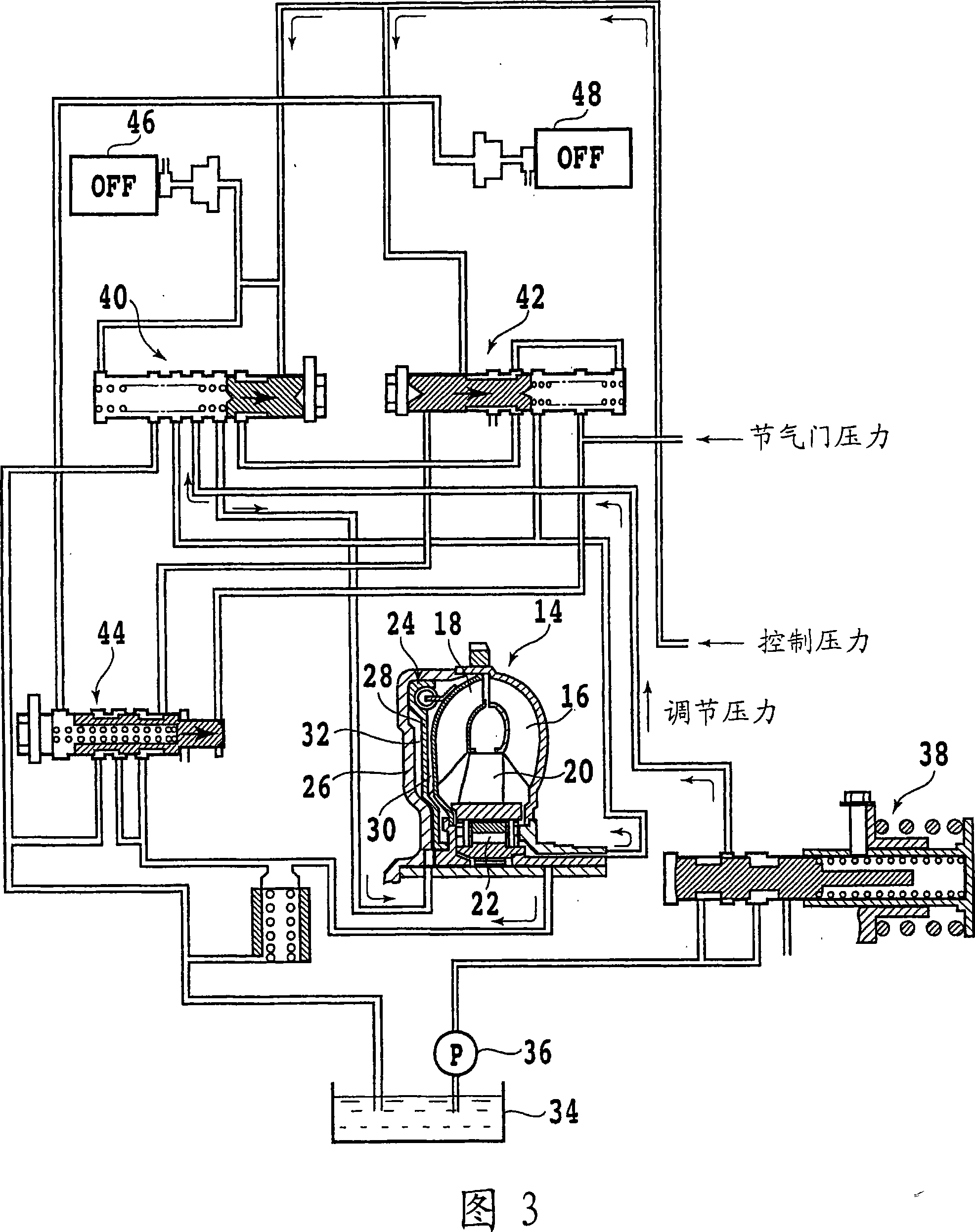
[0042] 3, there is shown a hydraulic circuit diagram of the torque converter 14 when the lock-up clutch is disengaged. FIG. 4 is a hydraulic circuit diagram of the torque converter 14 when the lock-up clutch is engaged.

[0043] As shown in FIG. 3, the torque converter 14 has: a pump wheel 16 connected to the crankshaft 10; a turbine wheel 18 connected to the main shaft 12; a stator 20 supported on a fixed part via a one-way clutch 22; and can be combi...


PUM


Abstract

control device for an automatic transmission (4) having a torque converter (14) with a lock-up clutch (24) provided between an engine (2) and the automatic transmission (4), and a lock-up control device for controlling an engaged condition of the lock-up clutch (24). The control device includes a plurality of different target slip ratio maps each having a plurality of target slip ratio characteristic lines of the lock-up clutch (24) predetermined according to a throttle angle, a first map selector for selecting one of the target slip ratio maps according to a running range, according to whether the running road is a level road / downhill road or an uphill road, and according to a gear position during running in the condition where an accelerator pedal is depressed, and a second map selector for selecting one of the target slip ratio maps according to a running range, according to whether the running road is a level road / uphill road or a downhill road, and according to a gear position during running in the condition where the accelerator pedal is undepressed.

Description

Technical field [0001] The present invention relates to a control device for an automatic transmission, and more particularly, to a control device for an automatic transmission that changes a target slip rate of a lock-up clutch according to a driving state. Background technique [0002] In automatic transmissions for vehicles, a hydraulic lock-up clutch that can mechanically directly connect the output shaft of the engine and the input shaft of the automatic transmission is provided in the torque converter. Generally, the lock-up clutch is locked under certain conditions. Improve the efficiency of the torque converter. [0003] In addition, the lock-up clutch is used to lock the lock-up clutch during deceleration, thereby transmitting the reverse driving force from the drive wheel side to the engine side, suppressing the rapid decrease of the engine speed, so as to restore the predetermined fuel during deceleration. The fuel cut performed up to the rotation speed is maintained f...

Claims


Application Information

Patent Timeline
Patent Type & Authority Applications(China)
IPC IPC(8): F16H61/14F16H59/24F16H59/66F16H59/70F16H59/18F16H59/42
CPCF16H59/66Y10S477/901F16H2061/145F16H59/24F16H2059/467F16H2061/0096F16H61/143
Inventor 斋藤吉晴高松正明
Owner HONDA MOTOR CO LTD
Why Eureka
Try Eureka