
Non-contact matrix switch for controlling a plurality of lighting equipments

A technology for lighting equipment and matrix switches, which is applied in general control systems, electronic switches, lighting devices, etc., can solve the problems of high wiring cost and complicated engineering construction, and achieve the effects of simple construction, convenient control and low cost.

Active Publication Date: 2008-07-30
南通金三角石墨制造有限公司
View PDF0 Cites 1 Cited by
  • Summary
  • Abstract
  • Description
  • Claims
  • Application Information

AI Technical Summary

Problems solved by technology

It can be seen that the control of multiple lighting devices by the above method is that one switch corresponds to one lighting device, or one switch corresponds to a group of lighting devices, and the direct control of one or some specified lighting devices cannot be realized randomly according to the needs.
Moreover, when the above-mentioned control method has a larger area and more lighting equipment, the engineering construction is more complicated, and the wiring cost is higher, so a lighting equipment control switch with simple construction and low cost is required.

Method used


Image

  • Non-contact matrix switch for controlling a plurality of lighting equipments
  • Non-contact matrix switch for controlling a plurality of lighting equipments

Examples


Embodiment Construction

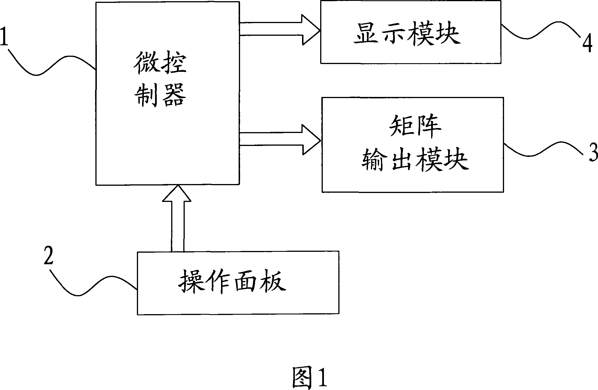
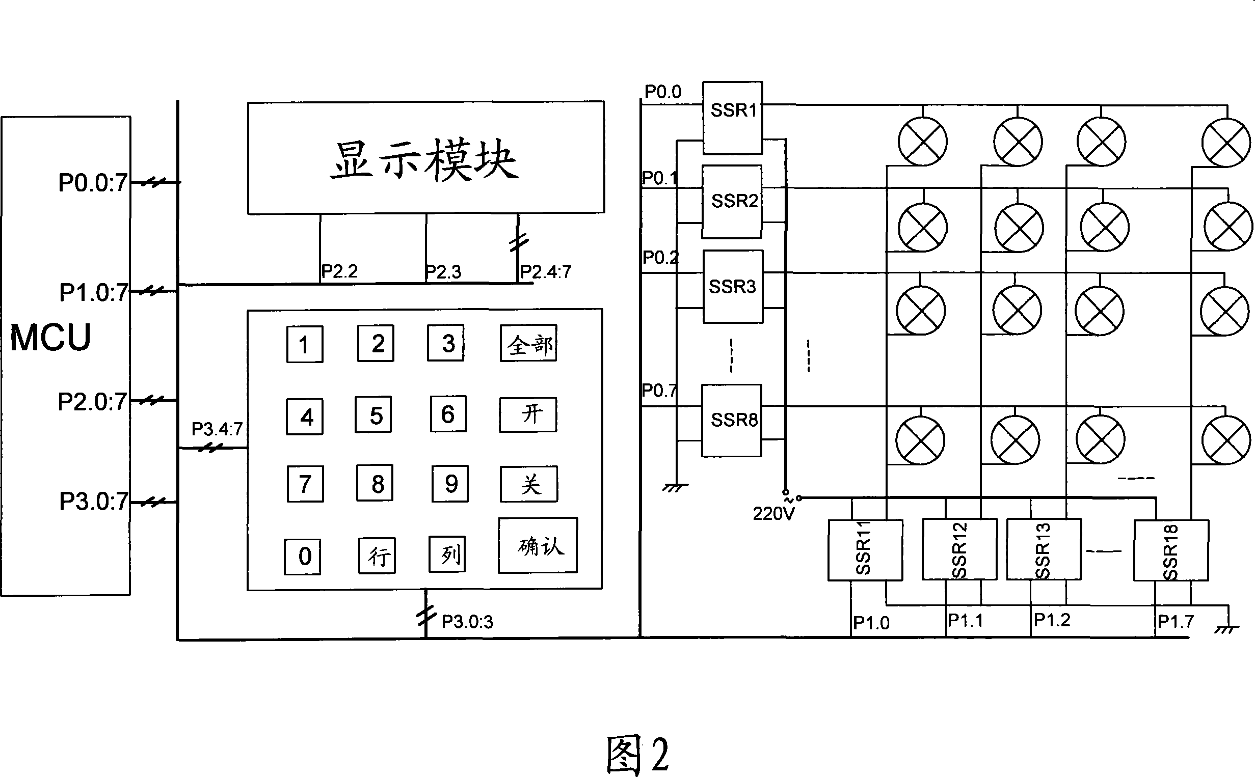
[0015] The non-contact matrix switch shown in Figure 1 mainly includes a microcontroller 1, an operation panel 2 for inputting control information to the microcontroller 1, a matrix output module 3 controlled by the microcontroller 1, and a display output module 3. The display module 4, wherein the matrix output module 3 includes N non-contact switch devices, each switch device has a signal input terminal connected to the output port of the microcontroller, and a power input terminal for connecting to the power supply and a signal output terminal for connecting with lighting equipment, the N switching devices are divided into two groups, one group includes K switching devices, and the other group includes L switching devices, wherein, N=K+L, In addition, K and L are both integers greater than 1. Therefore, the outputs of the two groups of switching devices form a K*L matrix column, so that the switching control of K*L lighting devices can be realized.

[0016] Below in conjunc...


PUM


Abstract

The invention relates to a non-contact matrix switch which is used for controlling a plurality of lighting devices. The switch comprises a micro-controller which is used for realizing core control, an operation panel with a plurality of operational keys, and a matrix output module of N non-contact switch elements. The N non-contact switch elements are divided into two groups. One group has K non-contact switch elements, the other group has L non-contact switch elements, wherein, N is equal to K+L, and K, L are the integral numbers which are greater than 1. The micro-controller controls the output of each switch element through the input information of the operation panel, thus realizing the control of the switches of K*L lighting devices. The invention can be used in the places where a large quantity of lighting devices are needed, and has the advantages of simple construction, low cost and convenient control.

Description

technical field [0001] The invention relates to a control switch suitable for controlling a large number of lighting equipment in large shopping malls, supermarkets, warehouses, entertainment places and the like. Background technique [0002] At present, in large shopping malls, supermarkets, warehouses, entertainment venues and other occasions where a large number of lighting equipment are used, the switch control of lighting equipment mainly uses contact switches and air switches. For example, directly control a single lighting device by using a mechanical 86-type single-connected one-position single-control switch, 86-type single-connected two-position single-control switch, or use an AC contactor to control a group of lighting devices. It can be seen that the control of multiple lighting devices by the above method is that one switch corresponds to one lighting device, or one switch corresponds to a group of lighting devices, and the direct control of one or some specifi...

Claims


Application Information

Patent Timeline
IPC IPC(8): H05B37/02H03K17/56G05B15/02
Inventor 陆卫忠班建民奚雪峰付保川
Owner 南通金三角石墨制造有限公司
Learn More