
48 head square spinning path

A spinning tunnel and tunnel technology, which is applied in the field of textile equipment accessories, can solve the problems of increasing capital investment, land occupation area and energy consumption, increasing floor space and energy consumption, etc., so as to ensure the spinning speed and quality stability, and reduce investment. , to ensure the effect of stability

Active Publication Date: 2010-04-21
JIANGYIN L V CHEM FIBER PROCESS TECH
View PDF4 Cites 0 Cited by
  • Summary
  • Abstract
  • Description
  • Claims
  • Application Information

AI Technical Summary

Problems solved by technology

In the past spandex spinning tunnels, generally 16 heads and 24 spinning heads were used as the main spinning, and the output of a single tunnel was about 30 tons per year (according to 40D). If it is necessary to increase the output, it is necessary to increase the spinning tunnel, winding machine, etc. The number of equipment, while increasing the energy consumption of the occupied area, thus greatly increasing the land occupied area and energy consumption of capital investment

Method used


Image

  • 48 head square spinning path
  • 48 head square spinning path
  • 48 head square spinning path

Examples


Embodiment Construction

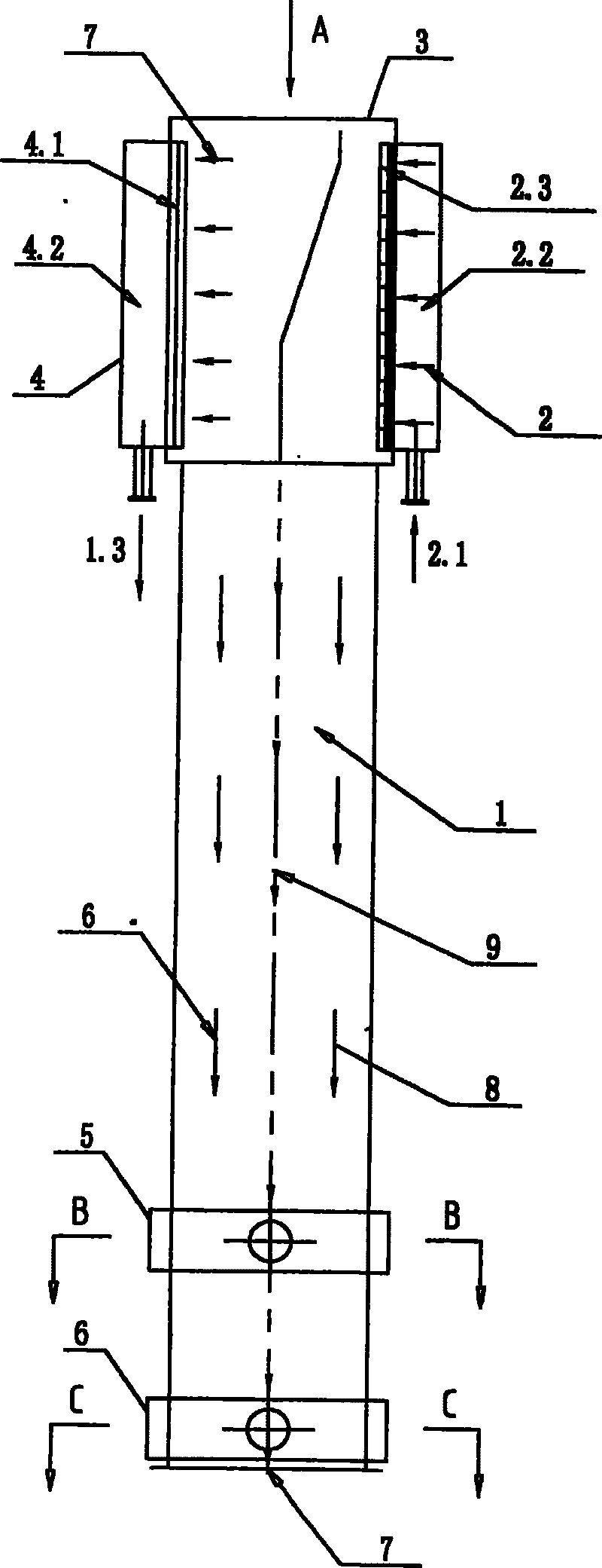
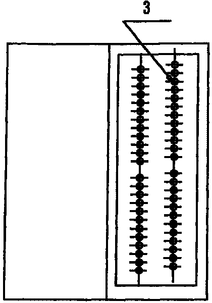
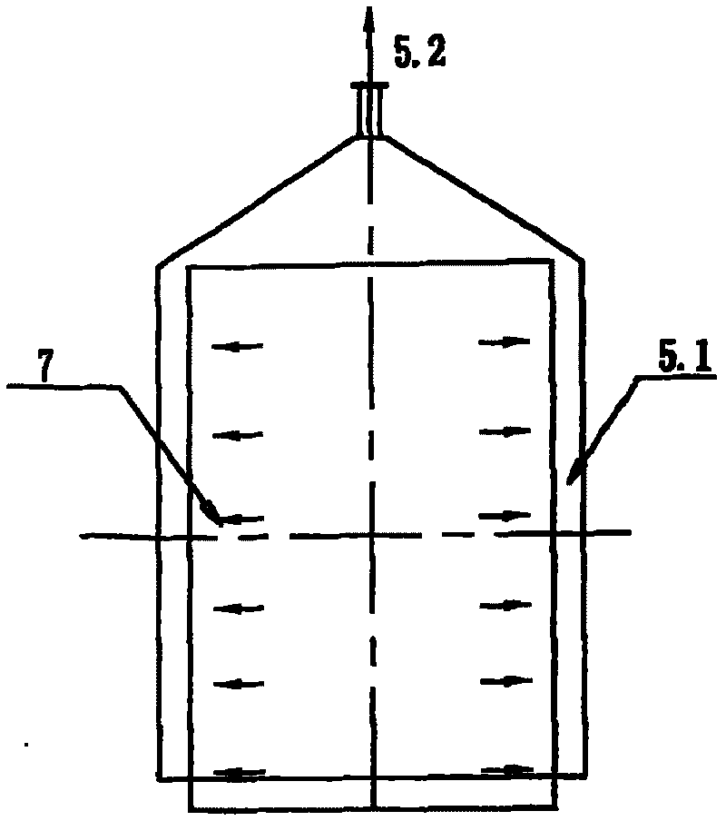
[0013] see Figure 1-2 , 48 square spinning tunnels of the present invention are mainly composed of square cylindrical tunnel body 1, upper side air inlet chamber 2, 48 spinning assemblies 3, upper side return air chamber 4, lower return air device 5 and lower nitrogen air curtain The device 6 is composed. The 48 spinning assemblies 3 are arranged on the top of the square cylindrical tunnel body 1, the upper air inlet chamber 2 and the upper return air chamber 4 are respectively arranged on the left and right sides of the top of the square cylindrical tunnel body 1, and the lower air return device 5 and the lower nitrogen air curtain device 6 are spaced up and down at the bottom of the square tube-shaped tunnel body 1 .

[0014] The upper air inlet chamber 2 is composed of an air inlet static plenum 2.2, a hot air inlet 2.1 and an air inlet rectifier 2.3. The hot air inlet 2.1 is arranged at the bottom of the air inlet static plenum 2.2, and the air inlet rectifier 2.3 is ar...


PUM


Abstract

The invention relates to a square spinning channel with 48 joints, which comprises a square tube shaped spinning channel body (1), an upper side air inletting cabinet (2), a spinning component with 48joints (3) and an upper side air returning cabinet (4), wherein the 48-joint spinning component (3) is mounted on the top of the square tube shaped spinning channel body (1), the upper side air inletting cabinet (2) and the upper side air returning cabinet are respectively mounted on the left side and the right side of the top of the square tube shaped spinning channel body (1). The square spinning channel with 48 joints is characterized in that a lower air returning device (5) and a lower nitrogen gas air curtain device (6) are mounted on the lower portion of the square tube shaped spinningchannel body (1), wherein the lower air returning device (5) and the lower nitrogen gas air curtain device (6) are mounted up and down in interval, the square spinning channel with 48 joints can greatlyimprove the output of the spinning under the precondition of slightly increasing the number of the spinning channel and winder device and the like.

Description

technical field [0001] The invention relates to a dry-process spandex spinning equipment. Specifically relates to a spandex spinning tunnel. It belongs to the field of textile equipment accessories. Background technique [0002] The spandex spinning tunnel is mainly used in the air distribution inside the spandex spinning equipment, the arrangement of the spandex tow and the heat tracing system. In the spandex spinning preparation process, its spinning speed is restricted by the polymer, and the spinning speed can reach up to 1200m / min. It has been impossible to significantly increase the spinning speed. In the past spandex spinning tunnels, generally 16 heads and 24 spinning heads were used as the main spinning, and the output of a single tunnel was about 30 tons per year (according to 40D). If it is necessary to increase the output, it is necessary to increase the spinning tunnel, winding machine, etc. The number of equipment, while increasing the energy consumption of...

Claims


Application Information

Patent Timeline
Patent Type & Authority Patents(China)
IPC IPC(8): D01D5/04D01D10/02
Inventor 李新立张益兴
Owner JIANGYIN L V CHEM FIBER PROCESS TECH
Learn More