
Heat pump clothes drying or clothes drying washing machine

A technology for washing machines and clothes dryers, applied in the field of clothes dryers or clothes dryers and washing machines, can solve the problems of affecting the surrounding environment, increasing compressor load, increasing temperature or humidity, etc., and achieving the effect of facilitating removal and cleaning

Active Publication Date: 2008-08-06
HAIER GRP CORP +1
View PDF2 Cites 34 Cited by
  • Summary
  • Abstract
  • Description
  • Claims
  • Application Information

AI Technical Summary

Problems solved by technology

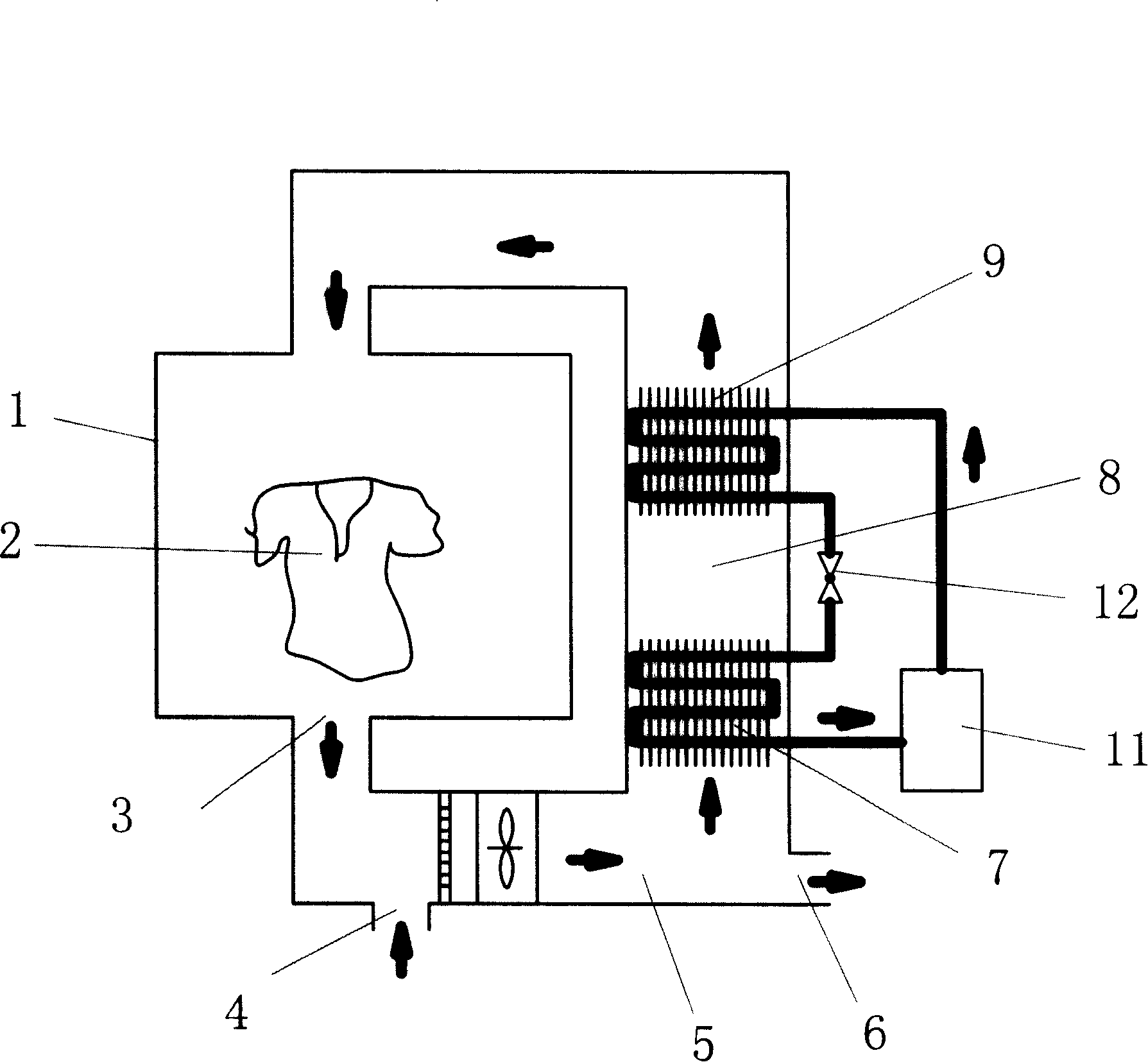
[0006] It is not difficult to see that although the invention prevents the overload of the compressor by sucking in external air, it will inevitably affect the surrounding environment, especially in hot summer, when the hot and humid air discharged from the outer tub is discharged to the outside of the clothes dryer. or increased humidity, which can make people feel uncomfortable
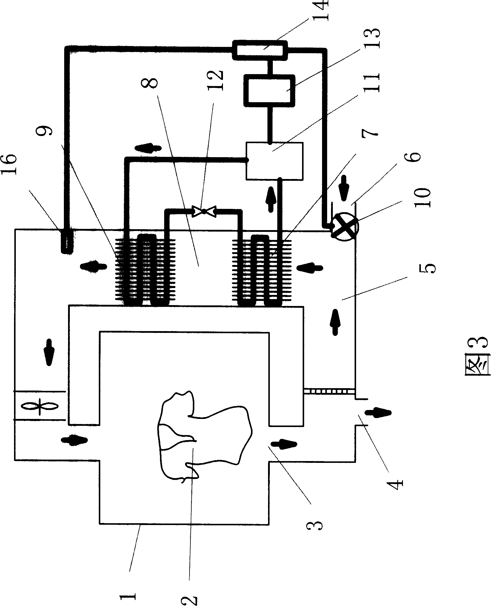
[0007] Furthermore, the state detection unit 16 is arranged on the downstream side of the heat radiator 9 (the downstream side mentioned here refers to the downstream side of the air circulation air duct of the clothes dryer, rather than the downstream side of the radiator 9 of the heat pump refrigerant circulation passage. side) or on the output pipeline of the compressor 11, whether it can correctly reflect the working status of the heat pump device. The pressure is too high, and the reason why the temperature on the output pipeline of the compressor is too high is not only related to the temperature and pressure of the gaseous refrigerant entering the compressor, but also related to the heat exchange of the radiator, that is, the refrigerant output by the compressor It is related to whether it can be cooled rapidly. If the heat of the radiator cannot be conducted away, the high temperature and pressure of the refrigerant in the radiator will also increase the load of the compressor and increase the temperature of the output pipeline.

Method used


Image

  • Heat pump clothes drying or clothes drying washing machine
  • Heat pump clothes drying or clothes drying washing machine
  • Heat pump clothes drying or clothes drying washing machine

Examples


Embodiment 1

[0036] Figure 5 , 6 is a schematic diagram of the structure of the heat pump drying clothes, or the washing and drying machine of the present invention and the hot air circulation air duct of the first embodiment. The heat pump dry clothes provided by the present invention, or dry clothes washing machine, comprises: the air circulation channel 24 that is formed by the drying chamber 21 that is provided with drum 20, blast chamber 22, heat exchange chamber 23; The air outlet 25 of drying chamber 21 Connect the heat exchange chamber 23, the blast chamber 22 is located in the air circulation channel, Figure 5 In the specific embodiment shown, the blast chamber 22 is arranged on the air inlet 26 of the drying chamber 21, and the outlet of the heat exchange chamber 23 is connected to the air inlet 26 of the drying chamber 21 through the blast chamber 22; The advantage of such an arrangement is that the drum 20 and the fan 28 can be driven simultaneously by a driving motor 27; of...

Embodiment 2

[0045] Fig. 7 is a schematic structural diagram of the heat pump drying clothes, or washing and drying machine and the hot air circulation air duct of the second embodiment of the present invention. The difference between the heat pump dry clothes or clothes dry washing machine provided in this embodiment and the first embodiment is that the temperature detection unit for detecting the working condition of the heat pump is arranged on the refrigerant output pipeline of the heat absorber. The state detection unit arranged on the refrigerant output pipeline of the heat absorber is a temperature detection unit or a pressure detection unit.

[0046] When the temperature sensor for monitoring the ambient temperature on the casing detects that the ambient temperature is lower than a certain set value, such as lower than 10°C in winter, and the temperature detection unit 39 for detecting the working condition of the heat pump detects the refrigerant in the heat absorber The temperatu...


PUM


Abstract

The invention relates to a dry cleaning washing machine and in particular relates to a heat pump cloth drying or cloth drying washing machine, which comprises an air circulation channel which is composed of a drying chamber, a blast chamber and a heat exchange chamber, wherein a heat absorber is arranged on one side of the heat exchange chamber which is close to the upper stream, a heat releaser is arranged on one side which is close to the lower stream, the heat absorber and the heat releaser are formed into a heat pump device through a compressor, a capillary tube and the like, an electronic control circuit is arranged, and an air inlet is arranged on the air circulation channel which connects the drying chamber and the heat exchange chamber, wherein an exhausting valve and a water-cooling condenser which are opened outside the machine are arranged on the upper stream of the heat absorber of the heat exchange chamber. When the environmental temperature is lower than a certain value, the control circuit controls the exhausting valve on the upper stream of the heat absorber to open to exhaust hot air outside the machine, when the environmental temperature is higher than a certain value, the control circuit controls the water-cooling condenser to operate, the temperature of air which enters into the heat absorber is lowered, which enables the temperature pressure of gaseous refrigerant which enters into the compressor to be comparatively low, and humid air is not exhausted outside the machine to deteriorate environment in hot summer.

Description

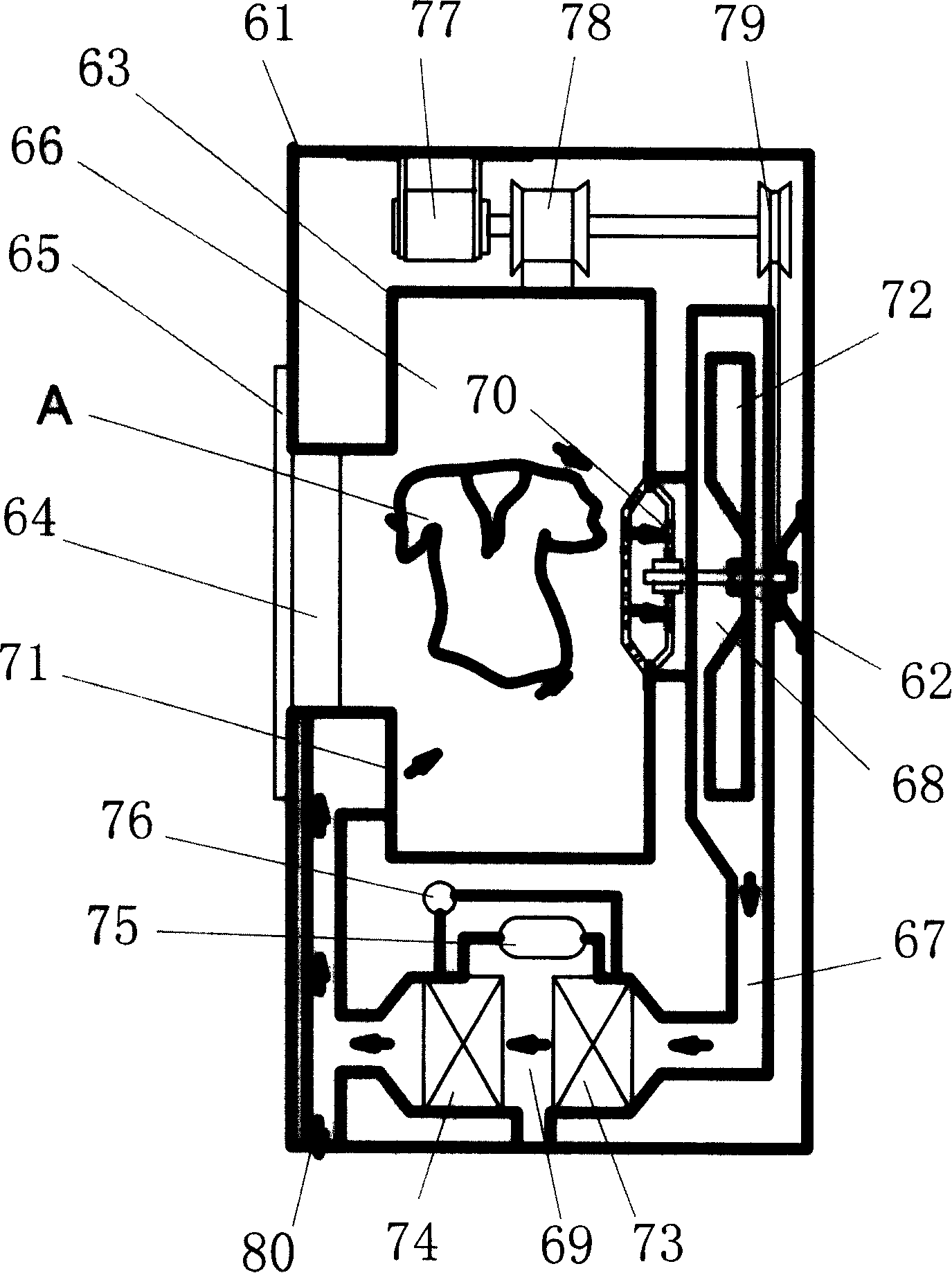
technical field [0001] The invention relates to a clothes dryer or a clothes dryer, in particular to a heat pump dryer or a clothes dryer which uses a heat pump device to dehumidify and heat air. Background technique [0002] The structure of the existing tumble dryer is as follows figure 1 As shown, a rotating drum 63 is provided inside the casing 61 , and a clothes input opening 64 is provided on the front of the rotating drum 63 , and can be opened / closed by a machine door 65 . The housing 61 is provided with an air circulation passage 67, and the air circulation passage 67 includes: a drying chamber 66, a blast chamber 68, a heat exchange chamber 69, and the like. The air in the drying chamber 66 flows into the blast chamber 68 from the air outlet 70 provided on its back wall, then passes through the heat exchange chamber 69, and enters the drying chamber 66 again from the air inlet 71 located at the front of the drying chamber 66. , cycle drying. A fan 72 is provided...

Claims


Application Information

Patent Timeline
Patent Type & Authority Applications(China)
IPC IPC(8): D06F58/10D06F58/02D06F58/20D06F58/24D06F58/28D06F25/00
Inventor 吕佩师席磊黄本财徐永洪
Owner HAIER GRP CORP
Learn More