

Mechanism for tooth profile modification force transformation
A technology of tooth profile and shape force, applied in the field of tooth profile modification force conversion mechanism, to achieve the effect of improving effective thermal efficiency, reducing mass, and saving external cooling facilities
- Summary
- Abstract
- Description
- Claims
- Application Information
AI Technical Summary
Problems solved by technology
Method used
Image

Examples
Embodiment Construction
[0057] Use the computer to select several models that may solve key technical problems from a large number of design schemes, draw accurately, perform kinematics simulation, analysis, and comparison, select one of the models of the swing piston internal combustion engine and the rotary piston internal combustion engine, and explore the tooth profile of the gear transmission Effective technical measures for shape modification. Examples of specific implementations are as follows:
[0058] 1. Example of the specific implementation of the tooth profile modification of the gear transmission for the oscillating piston internal combustion engine:
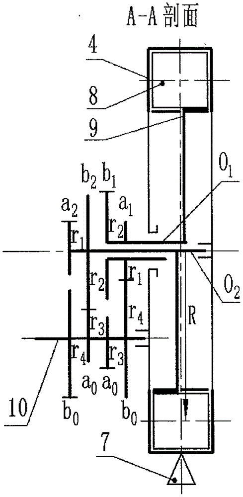
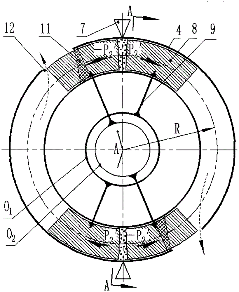
[0059] 1.1. Selection figure 1 , figure 2 Schematic diagram of the structure as an example. figure 2 for figure 1 The A-A section diagram.
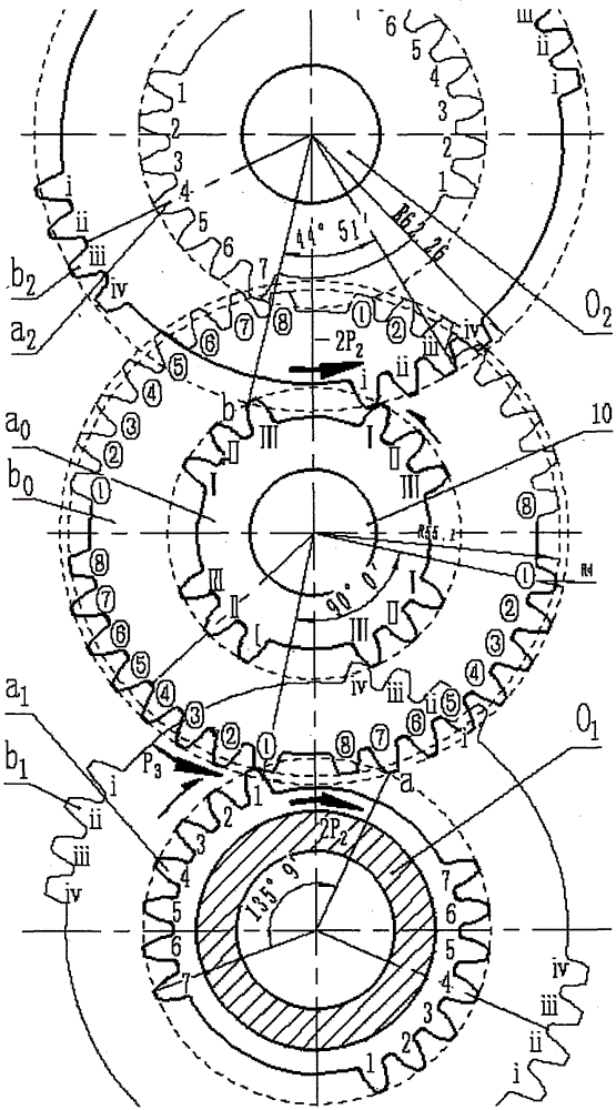
[0060] 1.2. Driving gear 1(z 1 ) and driven gear 2 (z 2 ) have the same number of teeth, and the number of teeth is = 26.
[0061] 1.3. If image 3 As shown, the driving gear z 1 As an inc...
PUM
 Abstract
Description
Claims
Application Information