Reducer depressurization system

A reducer and machine body technology, applied in the direction of mechanical equipment, transmission parts, belts/chains/gears, etc., can solve the problem that the reducer cannot achieve pressure equalization, and achieve the effect of reducing oil leakage, temperature and pressure

Inactive Publication Date: 2017-02-08
常州耐强传动机械有限公司
View PDF5 Cites 0 Cited by
  • Summary
  • Abstract
  • Description
  • Claims
  • Application Information

AI Technical Summary

Problems solved by technology

[0002] In a closed reducer, each pair of gears meshes with each other and generates heat due to friction. According to Boyle-Mariotte's law, as the operating time increases, the temperature inside the reducer case increases gradually, and the volume inside the reducer case does n

Method used


Image

  • Reducer depressurization system
  • Reducer depressurization system

Examples


Example Embodiment

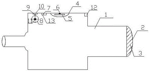
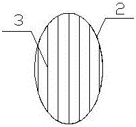
[0016] like figure 1 It is a structural schematic diagram of the present invention, figure 2 It is a schematic diagram of the structure of the ventilation hood of the present invention, a depressurization system of a reducer, including a body 1, the tail of the body 1 is provided with a ventilation hood 2, the ventilation hood 2 is provided with a dustproof device 3, and the inner top wall of the body 1 is provided There is a dust cover 4, a signal converter 7, a fan base 10 and a power port 12, and a temperature sensor 5 is arranged inside the dust cover 4, and the temperature sensor 5 is fixed on the inner top wall of the body 1 by a fixing device 6, and the fan The base 10 is connected with a bracket 9 by bolts, one end of the bracket 9 is fixed on the fan base 10, the other end is welded with a rotating shaft 11, the rotating shaft 11 is provided with fan blades 8, the temperature sensor 5, the signal converter 7, the rotating shaft 11 Both are connected with the power p...


PUM


Abstract

The invention relates to the technical field of reducers, in particular to a reducer depressurization system which comprises an engine body, wherein a ventilation hood is arranged at the tail of the engine body; an antidust device is arranged on the ventilation hood; a dust cover, a signal converter, a fan base and a power supply port are arranged on top wall of inner side of the engine body; a temperature sensor is arranged in the dust cover and is fixed on top wall of inner side of the engine body through a fixing device; a bracket is connected onto the fan base through a bolt; one end of the bracket is fixed on the fan base; a rotary shaft is arranged at the other end of the bracket; fan blades are arranged on the rotary shaft; the temperature sensor, the signal converter, the rotary shaft and the power supply port are connected through internal lines; and the power supply port provides power supply. According to the reducer depressurization system, a reducer provided with the ventilation hood is designed, and the fan is additionally arranged, so that the purpose of rapidly reducing internal temperature and pressure in the reducer is realized, and the oil leakage phenomenon is reduced.

Description

technical field [0001] The invention relates to the technical field of reducers, in particular to a reducer decompression system. Background technique [0002] In a closed reducer, each pair of gears meshes with each other and generates heat due to friction. According to Boyle-Mariotte's law, as the operating time increases, the temperature inside the reducer case increases gradually, and the volume inside the reducer case does not change. Change, so the pressure in the box increases accordingly, and the existing reducer does not have a ventilation cover, the reducer cannot achieve pressure equalization, and the lubricating oil in the box is splashed and sprinkled on the inner wall of the reducer box. Due to the relatively strong permeability of oil, under the pressure in the tank, where the seal is not tight, the oil will seep from there. Contents of the invention [0003] In order to overcome the existing deficiencies, the invention provides a reducer decompression syst...

Claims


Application Information

Patent Timeline
IPC IPC(8): F16H57/04F16H57/027
CPCF16H57/027F16H57/0413F16H57/0416
Inventor 周晓峰
Owner 常州耐强传动机械有限公司
Why Eureka
Try Eureka